7 - 24
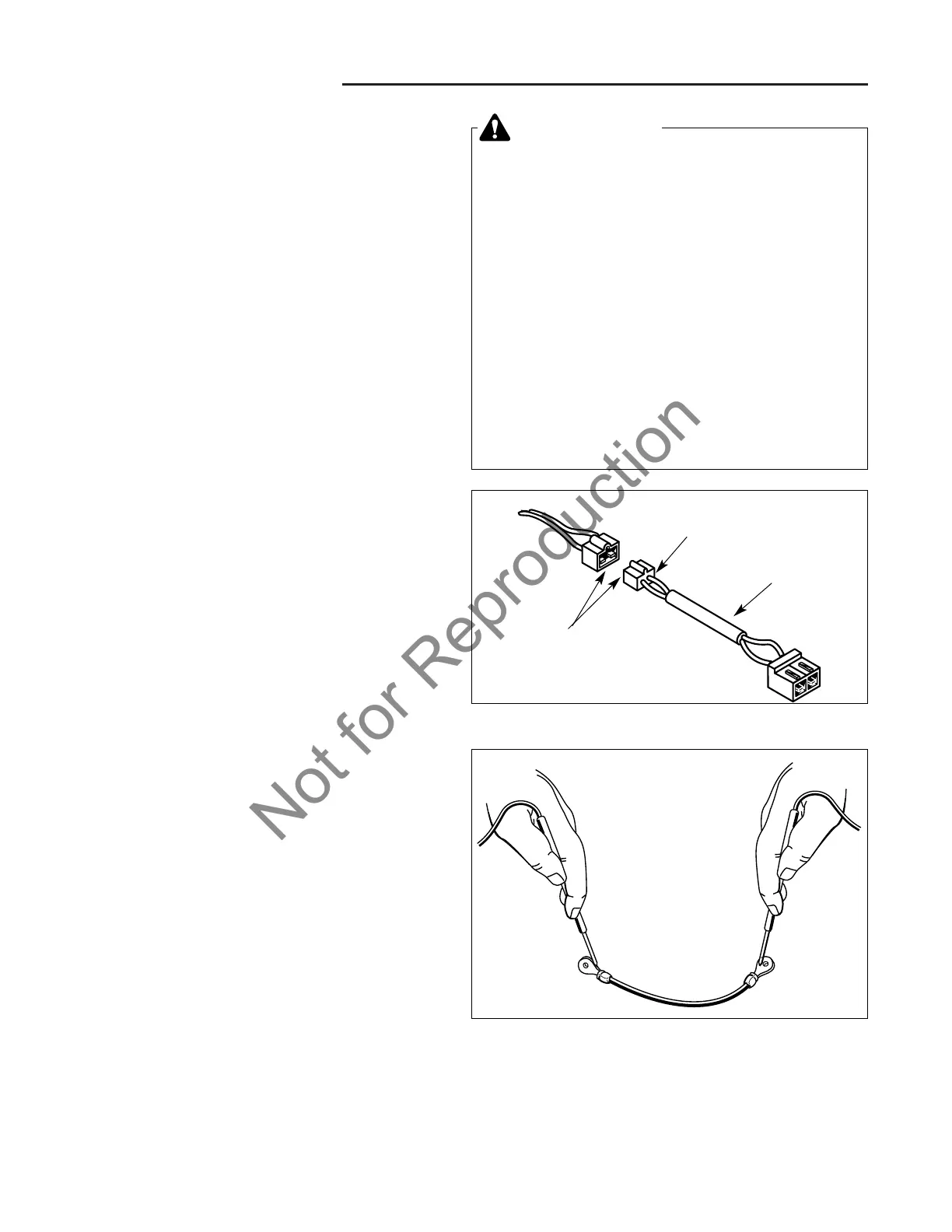
Figure 21. Testing Cable Continuity
Figure 20. Typical Wire Harness
Check for
Loose Wires
Inspect
Insulation
Check for
Corrosion
7 Electrical System Service
Component Tests
COMPONENT TESTS
General
The following tests should be used in conjunction with
this sections troubleshooting flow charts to efficiently
troubleshoot common electrical problems; however, if a
specific component is suspect, these tests can be used
independently of the flow chart and of each other.
A. Check/Clean Wires and Connectors
1. Check all wires for cracked or worn insulation.
2. Check all connectors, terminals, and receptacles for
loose wires or corrosion (Figure 20). Refer to the
exploded view diagrams for wire harness locations.
B. Check/Clean Ground Cable
1. Disconnect and secure the negative battery cable
(see Section 6, COMMON SERVICE PROCE-
DURES).
2. Disconnect the other end of the negative battery
cable (ground cable) from the engine.
3. Clean the battery and cable terminals with a wire
brush until the metal is shiny.
4. Using a VOM set to Ohm, test the continuity of the
cable (Figure 21). The VOM should register no more
than 2-3 ohm.
5. Clean the negative battery post and engine ground
with a wire brush until the metal is shiny.
6. Reattach the negative cable to the engine block and
then the negative battery terminal.
WARNING
Before beginning any test,
ALWAYS:
• Disconnect the spark plug wire.
• Block the wheels.
IN MOST CASES:
• Engage the parking brake.
• Turn the PTO switch OFF.
• Turn the ignition switch OFF.
• Place the ground speed control lever in
NEUTRAL (Peerless models only).
If a test procedure requires a configuration other
than the one listed above, instructions will be pro-
vided in that specific procedure.
Always reset the tractor to the configuration listed
above unless told otherwise.
 Loading...