6 Common Service Procedures
Rear Wheel Removal & Installation
6 - 6
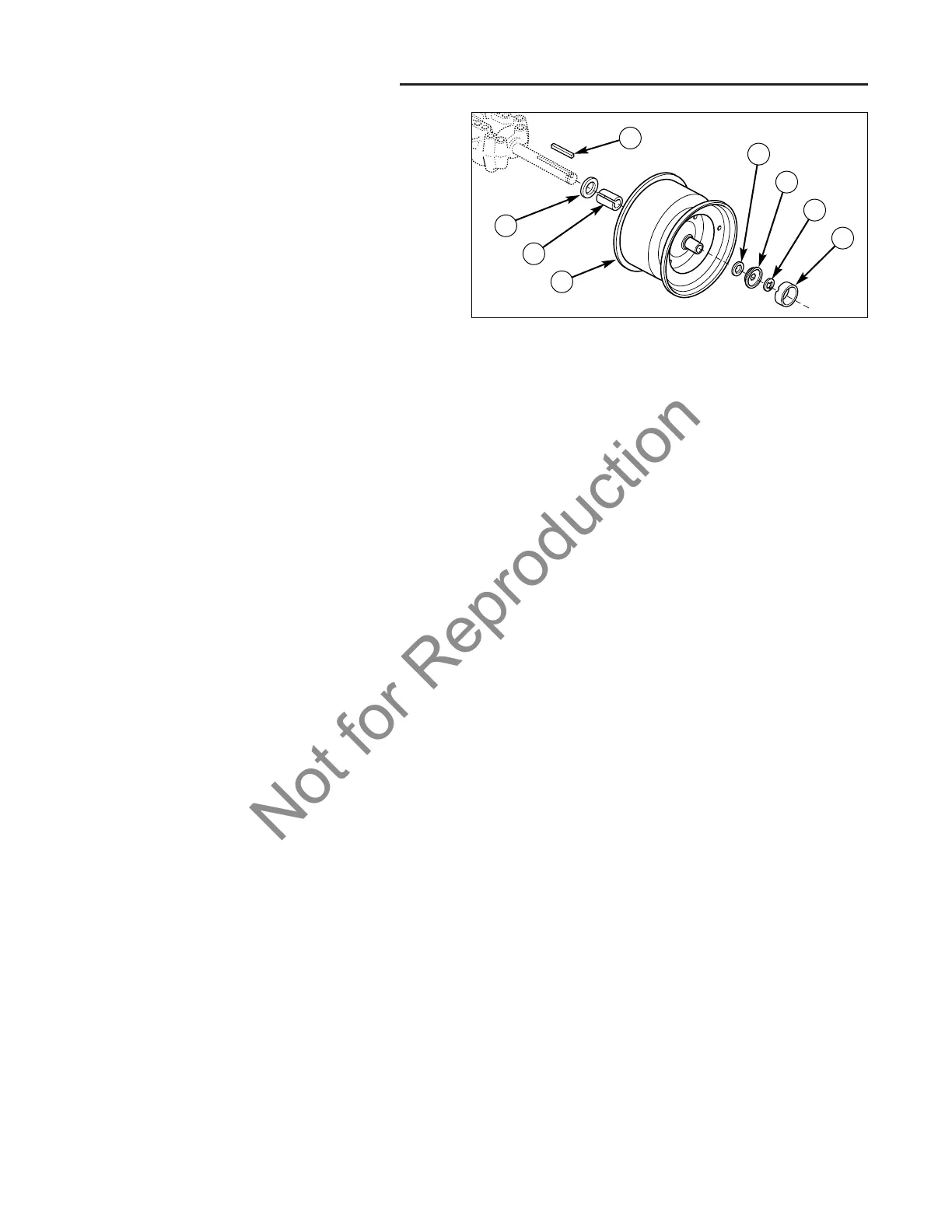
Figure 14. Wheel and Axle Assembly
A. Washer E. Hub Cap Retainer
B. Spacer F. E-Ring
C. Wheel G. Hub Cap
D. Washer H. Key
A
B
C
D
E
F
G
H
REAR WHEEL REMOVAL &
INSTALLATION
1. Remove the key and disconnect the spark plug wire
while working on the unit.
2. Engage the parking brake and block the front wheels.
3. Using a jack or chain hoist positioned at the center of
the rear frame, carefully jack the unit up until the rear
tires are approximately 1" - 2" off the ground.
NOTE: For overall unit stability during service, do not
jack rear end higher than required for wheel removal.
4. Support the rear of the unit on jack stands positioned
under the rear frame.
5. Remove the plastic hub cap (G, Figure 14).
6. Remove e-ring (F, Figure 14) using a screwdriver.
7. Remove the washers (D) and wheel (C).
NOTE: Your axle assembly may differ slightly from the
assembly pictured: washer (D, Figure 14) may be miss-
ing or doubled. This is adjusted on a tractor by tractor
basis during assembly to allow a small amount of axle
end-play.
8. Lubricate the axle shaft with anti-seize compound or
lithium grease.
9. See Figure 14 for assembly. Reinstall components in
reverse order of disassembly and lower the unit. Be
sure the key (H) is in place in the axle key-way.
 Loading...