14 - 19
14 Transmission Tear-Down
Assembly
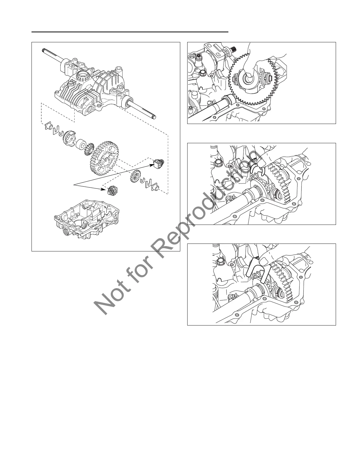
13. Install the differential assembly.
• See Figure 27. First assemble the smaller pinion
gears with the controlled traction mechanism into the
final drive gear. Note that the small tabs should be in
against the gear and not to the side.
• See Figure 27. Next install the larger side gears
being sure that if you have the differential lock, that
the gear with the notches is on the left and goes into
the differential lock slider.
• See Figure 27. Install the collar into the slider with
the recess facing out.
• See Figure 27. Install the slider, collar, and gear on
the left side of the differential gear.
• See Figure 28. Install the entire differential assem-
bly into the case lining up each sides axle one at a
time.
• See Figure 29. Install the c-ring in each side with a
magnet tool. Be sure they are in the proper groove.
It is easy to install them next to the splines where
they do not belong. The flat side should face in.
• See Figure 30. Install the retainers.
Figure 27. Differential Assembly
Pinion Assy.
DO NOT
Disassemble
Figure 30. Install Differential Retainers
Figure 29. Install C-Rings
Figure 28. Install Differential Assembly
 Loading...