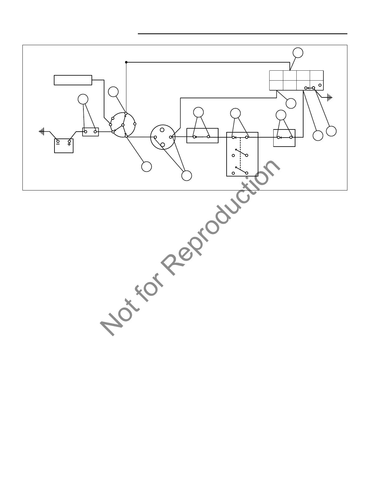
Figure 7. Cranking Circuit Linear Diagram
COMMON “NO START”
CIRCUIT TESTS
Cranking Circuit Test
Perform the following tests if the starter will not crank the
engine. The procedure below uses a VOM to show volt-
age at specific switches. If a switch is not transmitting
voltage across itself, it is defective and should be
replaced.
Test Instrument: VOM set to VDC.
Control positions:
Brake Pedal - Depressed (parking brake set)
PTO Switch - OFF
Seat - Occupied
Ignition Switch - Start Position
Battery: Both terminals connected.
Safety: Disconnect the lead from starter to prevent acci-
dental cranking. Secure away from the frame.
Procedure:
NOTE: Do not disconnect any of the switches or compo-
nents being tested. Probe connectors from the back, or
partially remove the connecter to probe the component
terminals.
1. Disconnect the lead from the starter motor and
secure away from the frame.
2. Connect the negative terminal of the VOM to the neg-
ative battery terminal.
3. Set the controls in the positions listed above.
4. Probe both sides of the circuit breaker (A, Figures 7
& 8). There should be current at both terminals.
5. Probe the L and S terminals of the key switch con-
nector (B, C). There should be current at both termi-
nals.
6. Check for current at both of the small terminals of the
solenoid (D).
7. Check for current at the foot pedal switch (E).
8. Check for current at the normally closed terminals of
the PTO switch (F).
9. Check for current at both seat switch terminals (G).
10. Check for current at the #1 and #7 terminal of the
interlock module (J). The #1 and #7 terminal must
receive power for the module to activate.
11. Check for current at the #3 (H) terminal of the inter-
lock module. A lack of current here means that the
wire connecting the #3 terminal and the seat switch is
broken.
12. Check for current at the #4 (I) terminal. If current is
present, the #4 grounding wire is defective. If no cur-
rent is present replace the module.
13. If current is detected at all specified locations, the
problem lies in one of the areas listed below. See
COMPONENT TESTS for specific testing proce-
dures:
* Defective Solenoid
• Defective Starter
• Defective Interlock Module
• Bad/Intermittent Ground
 Loading...