12
EN
ATYSp - 542001E - SOCOMEC
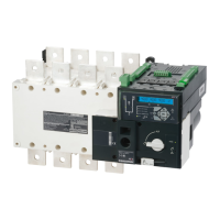
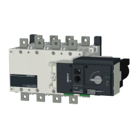
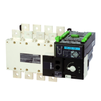
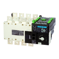
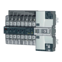
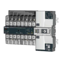
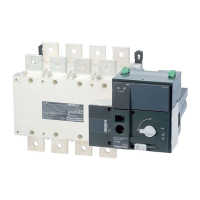
ATyS p
Motorised Source Changeover Switch
Automatic Transfer Switching Equipment
STEP 4
Preliminary operations
Check the following upon delivery and after removal of the
packaging:
•Packaging and contents are in good condition.
•The product reference corresponds to the order.
•Contents should include:
Qty 1 x ATyS p
Qty 1 x Emergency handle and fixing clip
Quick Start instruction sheet
Warning
Risk of electrocution, burns or injury to persons and /
or damage to equipment.
This Quick Start is intended for personnel trained in the
installation and commissioning of this product. For further
details refer to the product instruction manual available on
the SOCOMEC website.
•This product must always be installed and
commissioned by qualified and approved personnel.
•Maintenance and servicing operations should be
performed by trained and authorised personnel.
•Do not handle any control or power cables connected to
the product when voltage may be, or may become
present on the product, directly through the mains or
indirectly through external circuits.
•Always use an appropriate voltage detection device to
confirm the absence of voltage.
•Ensure that no metal objects are allowed to fall in the
cabinet (risk of electrical arcing).
Failure to observe good enginering practises as well as to
follow these safety instructions may expose the user and
others to serious injury or death.
Risk of damaging the device
•In case the product is dropped or damaged in any way it
is recommended to replace the complete product.
Accessories
•Bridging bars and connection kits.
•Control voltage transformer (400Vac -> 230Vac).
•DC power supply (12/24Vdc -> 230Vac).
•Mounting spacers to raise the product x 10mm.
•Phase barriers.
•Terminal shrouds / Terminal screens.
•Auxiliary contacts (Additional).
•Padlocking in 3 positions (I - O - II).
•Lockout accessories (RONIS - EL 11 AP).
•Door escutcheon frame.
•ATyS D20 Interface (remote control / display unit).
•RJ45 cable for ATyS D20 => ATyS p.
•Voltage sensing kit.
•Current transformers.
•Plug-in optional modules: RS485 MODBUS
communication, 2 inputs/2 outputs, Ethernet
communication, Ethernet communication + RS485
JBUS/MODBUS gateway, Analogue outputs, Pulse
outputs.
For further details refer to the product instruction manual
under chapter "Spares and Accessories"
quick start 125A-630A
EN
Clip for
storage of
the
emergency
handle
STEP 3
Dimensions in mm.
125 A 160 A 200 A 250 A 315 A 400 A 500 A 630 A
3 P 4 P 3 P 4 P 3 P 4 P 3 P 4 P 3 P 4 P 3 P 4 P 3 P 4 P 3 P 4 P
J 1 34 34 34 34 34 34 35 35 35 35 35 35 34 34 34 34
M 120 150 120 150 120 150 160 210 160 210 160 210 210 270 210 270
T 36 36 36 36 36 36 50 50 50 50 50 50 65 65 65 65
C 244 244 244 244 244 244 244 244 244 244 244 244 320 320 320 320
U 20 20 20 20 20 20 25 25 35 35 35 35 32 32 45 45
W 9 9 9 9 9 9 11 11 11 11 11 11 13 13 13 13
CA 10 10 10 10 10 10 15 15 15 15 15 15 20 20 20 20
UT
C
21
STEP 1
Installation
Door cut-out for front panel.
50.5
20
138
165
Caution:
Ensure that
the product is
installed on a
flat rigid
surface.
Ok Ok
STEP 3
STEP 4
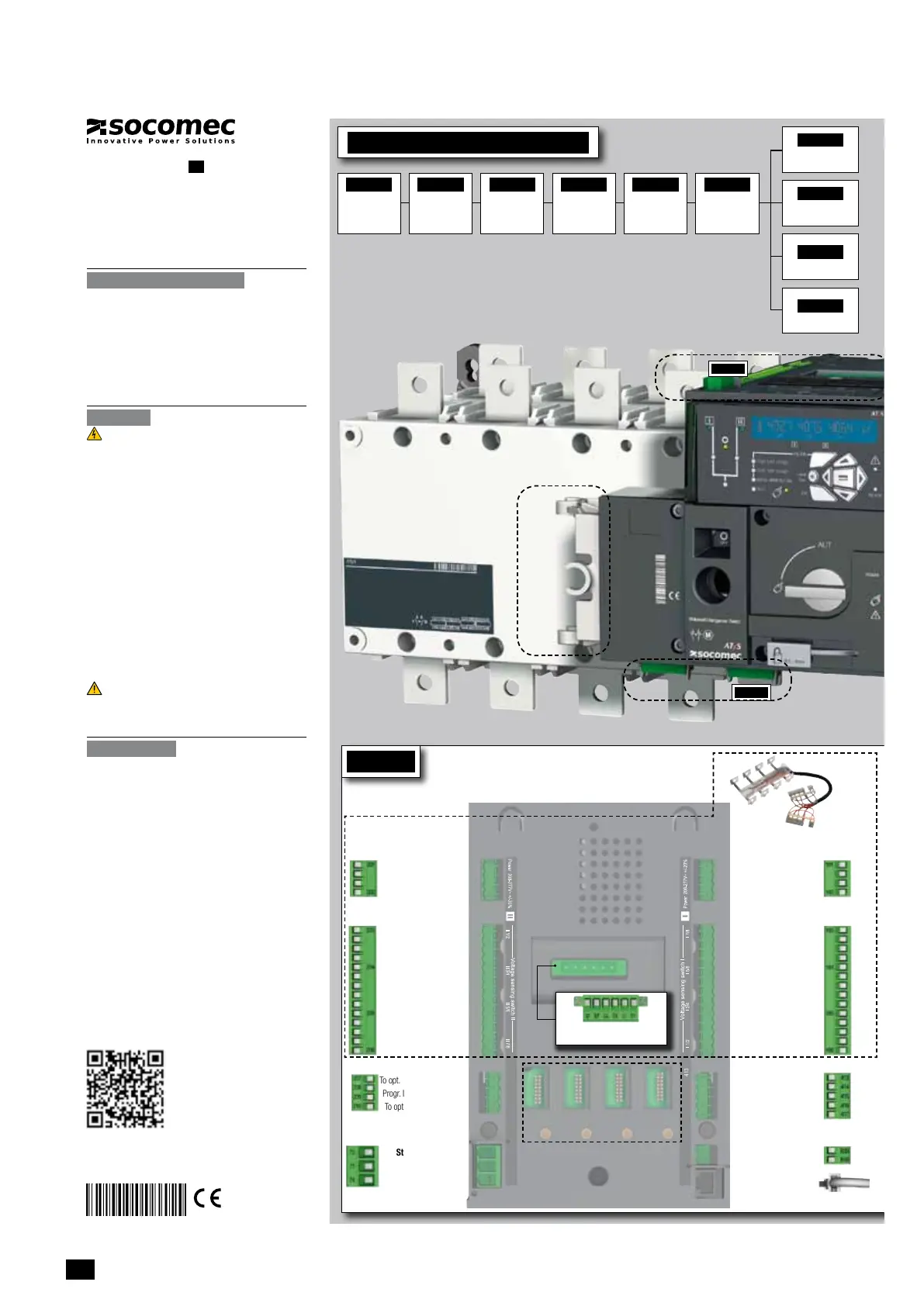
CONTROL / COMMAND Terminals
Ensure that the product is in Manual Mode.
Power Supply, Sensing and Control wiring (ATS Controller)
5
6
4
3 2
1
2
7
104 103
312313 314315 316317 63A64A 24 14 04 13
8 9
10
RJ
102 101
105106
414 413415416417
64B 63B
201 202
205 206204203
210209208207
12
13
14
15
11
1
F1
F2
19
20
16
17
18
23
23
24
24
72 71 74
I/1-2 I/3-4 I/5-6 I/7-8
II/1-2 II/3-4 II/5-6 II/7-8
LOAD
21
22
R1 R2 S1 S2 T1 T2
Opt. 3
Opt. 2
Opt. 1
4
Opt. 4
3
2
1
Connect the product with a cable of section of 1,5 to 2,5 mm
2
.
Screw M3 - Tightening torque: min.: 0.5 Nm - max.: 0.6 Nm
Example: Control wiring for a 400VAC application having a 3 phase and neutral supply.
1
2
1
preferred source
2
alternate source
1. Position 0 order
2. Position 1 order
3. Position 2 order
4. Zero position priority order
5.
Remote Control Enable (Priority over Auto)
6. Product Available output (Motor)
7. Position II aux contact
8. Position I aux contact
9. Position 0 aux contact
10. O/P to ATyS D20 remote unit
11. Programmable Output Contact.
By default set to ATS Product
Available - Normally Open
12-15. Programmable Inputs 1-4
16-17. Programmable Inputs 5-6
18. Aux. Supply (207/210) to be used
with ATyS optional I/O modules
19. Contact “Start/Stop Genset” : if S1
is not available the NC contact le
contact (71-72) is close
20. Contact “Start/Stop Genset” : if S1
is not available the NO contact le
contact (71-74) is open
21. Option Module Slots 1 to 4
22. Current Transformer incoming cable
connections
23. Voltage Sensing Inputs
24. Power Supply Inputs
Printing informations: 1 color Black. White paper 90g/m
2
.
Printing size: 420x297. Final size 210x297. This page visible first.
Non contractual document.
Subject to change without notice.
ATS Module
ControlInputs
(Programmable)
Programmable Inputs
To opt. Module/Common
Progr. Inputs (208-209)
To opt. Module positive
ATS Module
Output Contact
(Programmable)
Genset
Start/Stop Signal
NC
Common
NO
Remote interface
RJ45 - to ATyS D20
Dual auxiliary supply:
Uc 208-277V~ +/-20% 50/60Hz
Power comsumption: 22VA
See instruction sheet
ATS CONTROLLER
To D10
To D20
64B 63B
417 416 415 414 413
207 208 209 210
417 416 415 414 413
207 208 209 210
7172 74
7172 74
ATyS t
Dual auxiliary supply:
Uc 208-277V~ +/-20% 50/60Hz
Power comsumption: 22VA
See instruction sheet
ATS CONTROLLER
ATyS p
Dual auxiliary supply:
Uc 208-277V~ +/-20% 50/60Hz
Power comsumption: 22VA
See instruction sheet
ATS CONTROLLER
ATyS g
Dual auxiliary supply:
Uc 208-277V~ +/-20% 50/60Hz
Power comsumption: 22VA
See instruction sheet
ATS CONTROLLER
To D10
To D20
64B 63B
64B 63B
417 416 415 414 413
207 208 209 210
417 416 415 414 413
207 208 209 210
7172 74
ATyS t
Dual auxiliary supply:
Uc 208-277V~ +/-20% 50/60Hz
Power comsumption: 22VA
See instruction sheet
ATS CONTROLLER
ATyS p
Dual auxiliary supply:
Uc 208-277V~ +/-20% 50/60Hz
Power comsumption: 22VA
See instruction sheet
ATS CONTROLLER
ATyS g
Slots for optional modules
See on the back "Optional modules"
Recommanded to use SOCOMEC
Voltage Sensing Kit
(refer to ATyS p
accessories
for details)
ATS Power Supply
InputI
Power supply I - L/N
Power supply I - N/L
208-277VAC ±20%:
50/60 Hz
ATS Power Supply
InputII
Power supply II - L/N
Power supply II - N/L
208-277VAC ±20%:
50/60 Hz
ATS Voltage Sensing
Input
Source supply II
S II - Phase / Neutral
S II - Phase
S II - Phase
575 VAC (ph-ph) max
S II - Neutral / Phase
332 VAC (ph-n) max
ATS Voltage Sensing
Input
Source supply I
S I - Phase / Neutral
S I - Phase
S I - Phase
575 VAC (ph-ph) max
S I - Neutral / Phase
332 VAC (ph-n) max
ATyS D20
Remote Control /
Display Unit
Recommended
orientation
STEP 1
Cabinet / Back
Plate Installation
STEP 3
COMMAND /
CONTROL terminal
connections
STEP 2
Power Terminal
Connections
STEP 4
Power SUPPLY and
ATS Controller
Terminal
Connections
STEP 5
CHECK
STEP 6
PROGRAMMING
A - Software
B - Keypad
Installation and Commissioning
STEP 7A
AUT Mode
(Automatic Control)
STEP 7C
Manual Mode
STEP 7B
AUT Mode
(Remote Control)
STEP 7D
Padlocking Mode
Current Transformer
incomingcable connections
STEP 2
Power Terminal Connections
To be connected using terminal lugs, rigid or flexable busbars.
CA
W
M
Fix. 195
Fix. 180
==
J1
U
CA
W
T
U
U
FRAME B3 FRAME B4 FRAME B5
125 A 160 A 200 A 250 A 315 A 400 A 500 A 630 A
Minimum cable section Cu (mm
2
) at Ith
(IEC60947-1)
35 35 50 95 120 185 2
x
95 2
x1
20
RecommendedcablesectionCu(mm
2
)
at Ith
- - - - - -
2x30x5 2x40x5
Maximum cable section Cu (mm
2
)
50 95 120 150 240 240
2x185 2x300
Maximum Cu busbar width (mm)
25 25 25 32 32 32
50 50
Type of screw
M8 M8 M8 M10 M10 M10 M12 M12
Recommendedtighteningtorque(N.m)
8.3 8.3 8.3 20 20 20 40 40
Maximum tightening torque (N.m)
13 13 13 26 26 26 45 45
www.socomec.com
To download, brochures, catalogues
and technical manuals:
http://www.socomec.com/en/
documentation-atys-p
CORPORATE HQ CONTACT:
SOCOMEC SAS, 1-4 RUE DE WESTHOUSE, 67235 BENFELD, FRANCE
4. QUICKSTART
4.1. Quick Start ATySpFrameB3toB5(125Ato630A)
 Loading...