EN
ATYSp - 542001E - SOCOMEC
Remote control logic
Remote switching operation can be driven in AUT mode by external volt free contacts as described above using
input contacts 312 to 317.
Depending on the wiring conguration there are two types of logic that may be applied to the ATySp.
• Impulse logic or
• Contactor logic.
In remote control, the ATySp inputs give priority to orders I and II over 0 therefore contactor logic can be implemented
by simply bridging terminals 316 and 317.
(NOTE: 313 – 317 closed / Force ATyS to OFF Position, takes priority over all other orders no matter of the control logic used.)
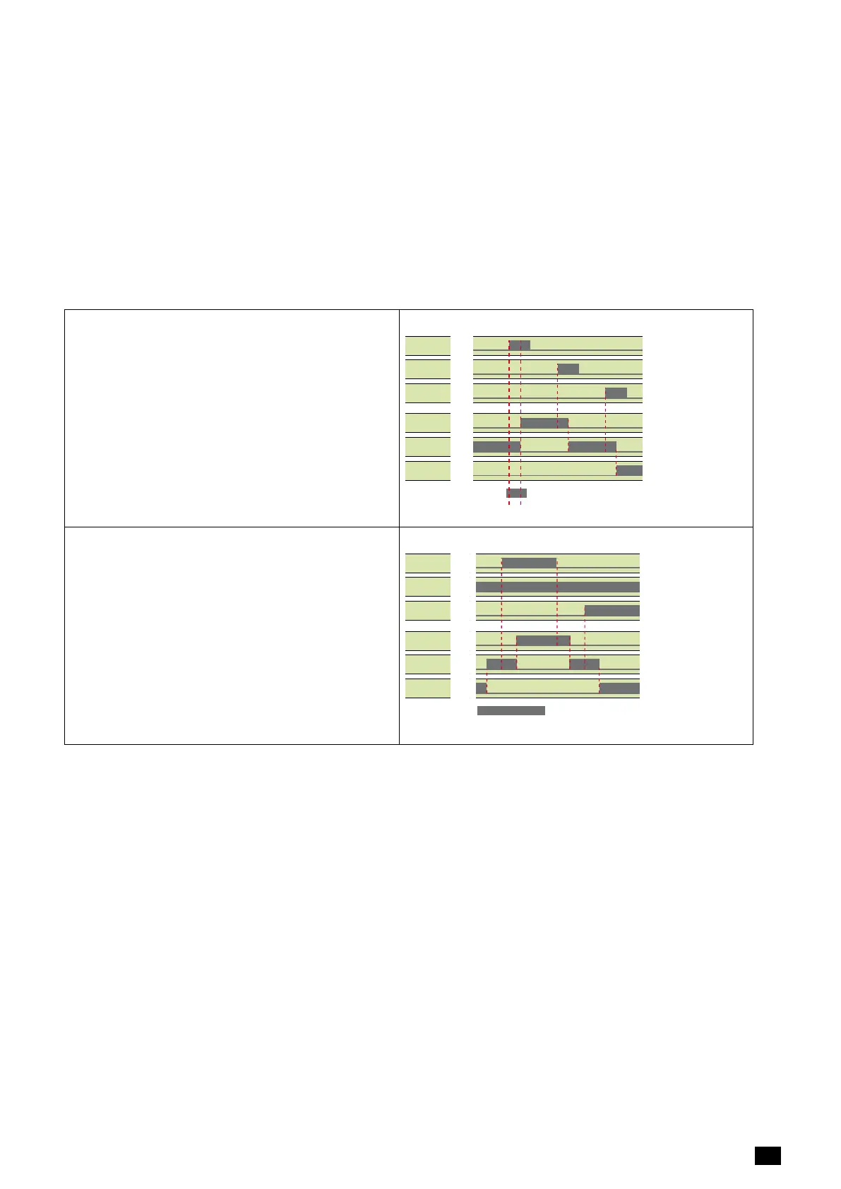
Impulselogic:
The ATySp is driven to a stable position (I – O – II) after
receiving an impulse order.
• A switching command of at least 60 ms is
necessary to initiate the switching operation.
• Orders I and II have priority over order 0.
Note: The logic diagrams exclude the transfer times.
Imp. ≥60ms
order I
position I
order 0
position 0
order II
position II
Impulse logic
(Note: Excludes position switching delays)
ContactorLogic:
The ATySp is driven to a specic position (I or II) for as
long as the order is maintained.
• Order O is maintained. (Bridge 316 – 317)
• Orders I and II have priority over order 0.
• Orders I and II have equal priority.
(1st order received is held until no longer
maintained).
• If order I or II disappears, the device returns to
zero position. (With the power supply available).
maintened
order I
position I
order 0
position 0
order II
position II
Contactor logic
(Note: Excludes position switching delays)
8.2.4.Programmableinputs
Description
Conguration of all programmable inputs is recommended to be done using the EasyCong Software available
for download on the Socomec Website. Communication with the ATySp is possible either through the Modbus
or Ethernet modules that are available as an option. Alternatively the parameters may also be congured directly
through the keypad on the front of the ATS controller.
• Pin413: Input In1, Programmable Input 1
• Pin414: Input In2 , Programmable Input 2
• Pin415: Input In3, Programmable Input 3
• Pin416: Input In4, Programmable Input 4
• Pin417: Common. Common supply for programmable inputs 1–4on terminals 413 to 416.
• Pin207:Common. Common supply for programmable inputs 5 – 6 on terminals 208 to 209.
• Pin208: Input In5, Programmable Input 5
• Pin209: Input In6, Programmable Input 6
NOTE: Details of the programmable inputs, see page 94.
 Loading...