EN
ATYSp - 542001E - SOCOMEC
7.4.2. Sensingkitwiringdiagram(standard)
BottomincomingwithTopOutgoing
• Black Wires -> Switch I
• Red Wires -> Switch II
Wiringnumbers:
Wire numbering has been determined in accordance to
the power switch terminals
TopIncomingwithBottomOutgoing
• Black Wires -> Switch II
• Red Wires -> Switch I
Example:
Black and red wire numbers 1-2 are always connected
to terminals 1 or 2 from switch I or II
II
1357
2468
630 A
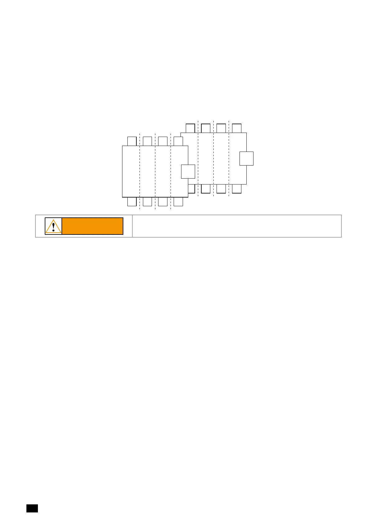
Kit connection on
power switches terminals
Example: 4 wires kit (4 poles)
Connection on power supply and control module
800 A
102101 106105104103
I
1357
2468
7-8 5-6 3-4 1-27-8 5-6 3-4
Red wires Black wires
1-2
1-2 3-4 5-6 7-8
1-2 3-4 5-6 7-8
1-2 3-4 5-6 7-8
1-2 3-4 5-6 7-8
ABAB
mechanical cables
support
202201206 205 204 203
CAUTION
Verify kit orientation before mounting the kit.
 Loading...