5-29
DSC-F707
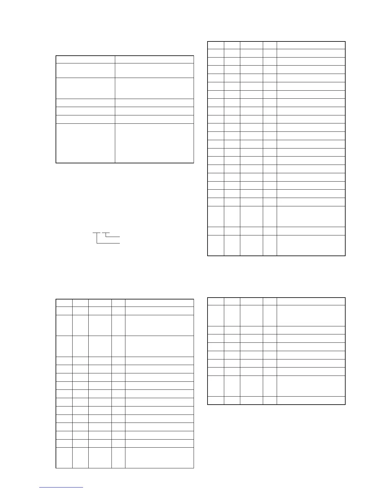
20. Strobe White Balance Adjustment
Adjust the white balance when the strobe light flashed.
Mode CAMERA
Subject Flash adjustment box (Note 3)
(50 cm from the front of lens)
Measurement Point Displayed data of page: 1 (Note
4) and page: F, address: E2, E6,
EA, EE
Measuring Instrument Adjusting remote commander
Adjustment Page F
Adjustment Address 90 to 93, DC to EF
Specified Value Y level data 1: 07 to 16
Y level data 2: 07 to 10
R-Y level data:
FA to FF or 00 to 06 (Note 4)
B-Y level data:
FA to FF or 00 to 06 (Note 4)
Note 1: Check that the data of page: 6, address: 02 is “00”.
If not, turn the power of unit OFF/ON.
Note 2: Perform this adjustment in the Flash adjustment box.
Restrict external light to enter the Flash adjustment box
as less as possible.
Note 3: Refer to “4. Preparing the Flash adjustment box”.
(See page 5-7)
Note 4: The right four digits of the page: 1 displayed data of the
adjusting remote commander.
1:XX:XX
B-Y level data
R-Y level data
Note 5: “Strobe White Balance Adjustment” is available only
once after the power is turned on. Turn the power off,
then on again if the adjustment is retried.
Switch setting:
1) FLASH (Control button) .............. ON
Adjusting method:
Order Page Address Data Procedure
1 0 01 01
2
Perform “Data setting during
camera system adjustment”.
(Refer to page 5-13)
32 04
Set the bit value of bit4 is
“1”, and press PAUSE
button. (Note 6)
4 6 90 00
5 6 91 00
66 92FF
76 93FF
86 6C01
96 2C01
10 6 01 79 Press PAUSE button.
11 6 07 Check the data changes to “01”.
12 6 01 67 Press PAUSE button.
13 Check the flashing.
14 6 02 Check the data changes to “01”.
15 F E2
Check that the displayed data
satisfies the Y level data 1
specified value.
16 6 01 00 Press PAUSE button.
17 6 01 67 Press PAUSE button.
18 Check the flashing.
19 6 02 Check the data changes to “01”.
20 6 01 00 Press PAUSE button.
21 6 01 67 Press PAUSE button.
22 Check the flashing.
23 6 02 Check the data changes to “01”.
24 6 01 00 Press PAUSE button.
25 6 01 67 Press PAUSE button.
26 Check the flashing.
27 6 02 Check the data changes to “01”.
28 6 01 00 Press PAUSE button.
29 6 01 B9 Press PAUSE button. (Note 7)
30 Check the flashing.
31 6 02 Check the data changes to “01”.
32 6 01 00 Press PAUSE button.
33 6 01 E7 Press PAUSE button.
34 Check the flashing.
35 6 02 Check the data changes to “01”.
36 F
E6 Check that the displayed data
EA satisfies the Y level data 2
EE specified value.
37 0 03 02
38 1
Check that the R-Y, B-Y
level data (Note 4) satisfies
the specified value.
Note 6: For the bit values, refer to “5-2. SERVICE MODE”, “2-
3. 2. Bit value discrimination”
Note 7: The adjustment data will be automatically input to page:
F, address: 90 to 93 and DC to EF.
Processing after Completing Adjustment:
Order Page Address Data Procedure
12 04
Set the bit value of bit4 is
“0”, and press PAUSE
button. (Note 6)
2 6 01 00 Press PAUSE button.
36 2C00
46 6C00
5 6 92 00
6 6 93 00
7 0 03 00
8
Release the data setting
performed at step 2.
(Refer to page 5-13)
9 0 01 00

 Loading...