5-31
DSC-F707
1-5. LCD SYSTEM ADJUSTMENTS
Before perform the camera system adjustments, check that the
specified values of “VIDEO SYSTEM ADJUSTMENTS” are sat-
isfied.
Note 1: Taken an extreme care not to destroy the liquid crystal
display module by static electricity when replacing it.
Note 2: Set the LCD BRIGHTENSS (SET UP setting) to the
NORMAL.
[Adjusting connector]
Most of the measuring points for adjusting the LCD system are
concentrated in CN305 of the FR-181 board.
Connect the Measuring Instruments via the CPC-12 jig (J-6082-
436-A).
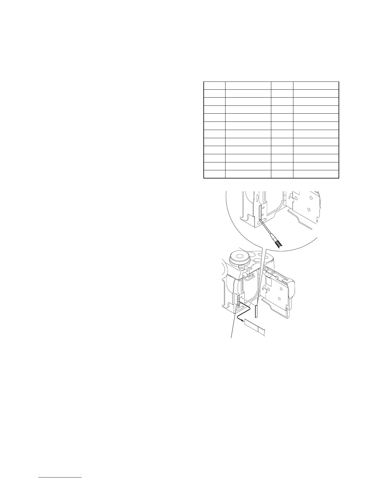
The following table shows the Pin No. and signal name of CN305.
Pin No. Signal Name Pin No. Signal Name
1 BL_L1 12 LANC_OUT
2 N.C. 13 MAKER_RECOG
3 N. C. 14 N.C.
4 REG_GND 15 N.C.
5 N. C. 16 N.C.
6 BL_L2 17 N.C.
7 PANEL_HSY 18 N.C.
8 PANEL_COM 19 EVF_BL
9 PANEL_VG 20 EVF_BL_4.75V
10 CPC_UNREG 21 EVF_VG
11 LANC_IN 22 EVF_VCO
Fig. 5-1-21
CPC cover
CPC-12 jig
(J-6082-436-A)
FR-181 board
CN305
22
1

 Loading...