5-4
DSC-F707
1-1-2. Preparations
Note 1: For details of how remove the cabinet and boards, refer
to “2. DISASSEMBLY”.
Note 2: When performing only the adjustments, the lens block
and boards need not be disassemble.
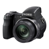
1) Connect the equipment for adjustments according to Fig. 5-1-
5.
2) Connect the Adjusting remote commander to the FR-181 board
CN305 via CPC-12 jig (J-6082-436-A). (See Fig. 5-1-3)
Note 3: Setting the “Forced CAMERA mode power ON” Mode
1) Select page: 0, address: 01, and set data: 01.
2) Select page: D, address: 10, set data: 01, and press
the PAUSE button of the adjusting remote com-
mander.
The above procedure will enable the camera power
to be turned on. After completing adjustments, be
sure to exit the “Forced CAMERA mode power ON
Mode”.
Note 4: Exiting the “Forced CAMERA mode power ON Mode”
1) Select page: 0, address: 01, and set data: 01.
2) Select page: D, address: 10, set data: 00, and press
the PAUSE button of the adjusting remote com-
mander.
3) Select page: 0, address: 01, and set data: 00.
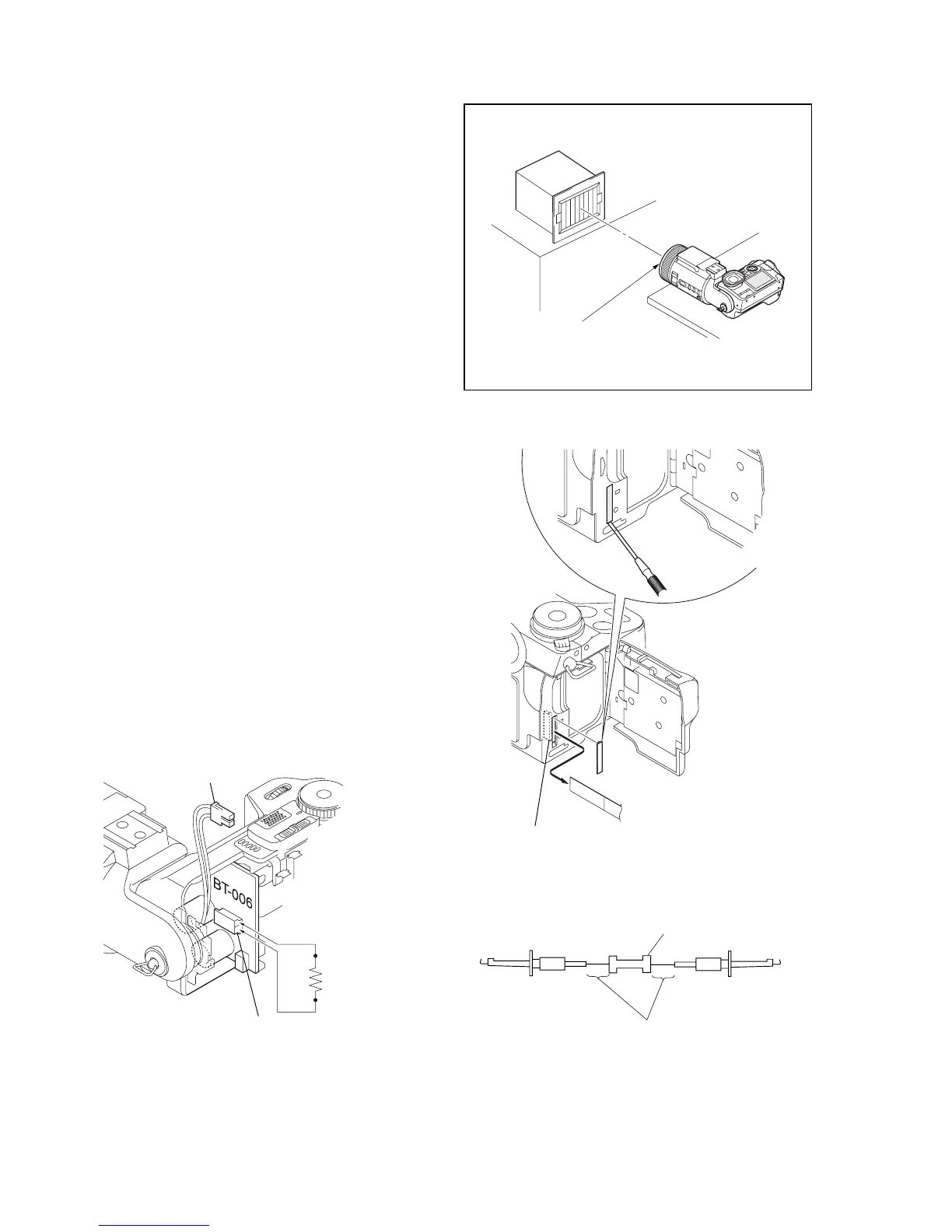
1-1-3. Discharging of the Flashlight Power Supply
The capacitor which is used as power supply of flashlight is charged
with 200 V to 300 V voltage. Discharge this voltage before start-
ing disassembly in order to protect service engineers from electric
shock during disassembly.
Discharge procedure
1. Remove the FR-181 board, and disconnect the harness from
CN404 on the BT-006 board.
2. Fabricate the short jig as shown in Fig. 5-1-5 locally by your-
self. Connect the short jig to the pin 1 and pin 2 of CN404
on the BT-006 board. Allow ten seconds to discharge the volt-
age.
Fig. 5-1-5
Fig. 5-1-3
1 kΩ/1 W
Wrap insulating tape.
Fig. 5-1-4
Fig. 5-1-2
R:1 kΩ/1 W
(Part code:
1-215-869-11)
CN404
Harness
Front of the lens
Pattern box
L
L=About 30 cm
CPC cover
CPC-12 jig
(J-6082-436-A)
FR-181 board
CN305
22
1

 Loading...