2-4
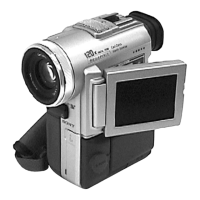
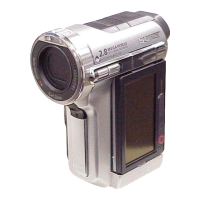
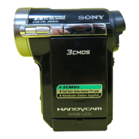
DCR-PC103E/PC104E/PC105/PC105E
2-5. ST CABINET (UPPER) ASSEMBLY
2-4. CABINET (L)
5
Cabinet (L)
6
Jack cover (L) assembly
2
Flip over the jack cover
(L) assembly.
4
Three screws
(M1.7
×
2.5),
lock ace, p2
3
Screw
(M1.7
×
2.5),
lock ace, p2
1
Screw
(M1.7
×
4),
lock ace, p2
1
Push the portion
A
in the
direction of the arrow to open
the Flash.
Short jig (R: 1k
Ω
/1W)
A
K
3
EG grip
(M1.7
×
2.5)
2
EG grip
(M1.7
×
2.5)
6
ST cabinet (upper)
assembly
3
ST cabinet (N)
assembly
5
Two claws
4
Two claws
Caution
Note: The power supply capacitor of the flash unit is charged to the high tension
voltage as high as 300 V at a maximum. You will get electrical shock when
you touch the terminal of the charged capacitor . The charged potential
remains even after the main power of the machine is turned off. Discharge
the remaining power in the capacitor referring to Service Note
(See page 1-2). High-voltage cautions. Short jig (R: 1k
Ω
/1W)
1
EG grip
(M1.7
×
2.5)
2
EG grip
(M1.7
×
2.5)
(PC103E/PC104E)
(PC105/PC105E)
A
Xenon tube
Accessory shoe GND

 Loading...


