33
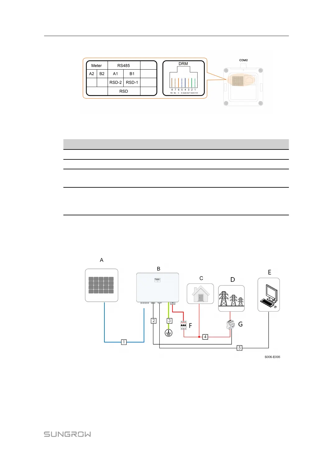
figure 5-2 Label of COM2 Terminal
table 5-2 Label Description of COM2 Terminal
Label
Description
Meter
A2, B2
For the smart energy meter
RS485-1
A1, B1
Reserved
RSD
RSD-1,
RSD-2
Reserved
DRM
R, C, D4/8,
D3/7, D2/6,
D1/5
For external Demand Response Enabling Device ("AU"/
"NZ")
5.3 Electrical Connection Overview
The electrical connection should be realized as follows:
(A) PV string (B) Inverter (C) Loads
(D) Grid (E) External device (F) AC circuit breaker
(G) Smart energy meter
The electrical connection should be realized as follows(Includes optimizer):
User Manual 5 Electrical Connection
 Loading...