TB9300 Installation and Operation Manual Replacing Modules 117
© Tait International Limited April 2024
3. Tighten the nut on the SMA connector to a torque of 5lbf·in
(0.6N·m).
4. Carry out the instructions in “Final Reassembly” on page 121.
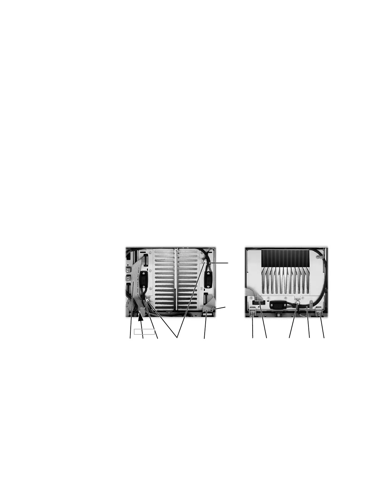
8.4 Replacing a Power Amplifier
Notice Before removing a PA, disconnect the DC input and RF input
first, followed by the RF output. After refitting the PA, reconnect the RF
output first, followed by the RF input, and then the DC input.
Removal 1. If you have not already done so, carry out the instructions in “Pre-
liminary Disassembly” on page 114.
2. At the front of the PA, unplug the DC input cable
b and the RF input
cable
c, and move both cables to one side. Unplug both ends of the
system control bus cable
d and remove it.
3. At the rear of the PA, unplug the RF output cable.
4. Loosen the screw securing the retaining clamp(s)
e and rotate the
clamp(s) through 90° to clear the module.
5. Slide the PA out of the subrack, taking care not to damage any of the
cables.
Refitting 1. Slide the replacement PA into the subrack and secure it with the
retaining clamp(s).
2. At the rear of the PA, connect the RF output cable.
3. At the front of the PA, connect the RF input cable, followed by the
DC input cable.
4. Reconnect all the other front and rear panel cables previously
disconnected. Ensure the front panel cables are positioned correctly,
and retained where required by the cable retaining clips in the top of
b
e
d
c
b
b
d
dec
e
e
50W PA 100W PA
(obscured)
f

 Loading...


