TB9300 Installation and Operation Manual Description 27
© Tait International Limited April 2024
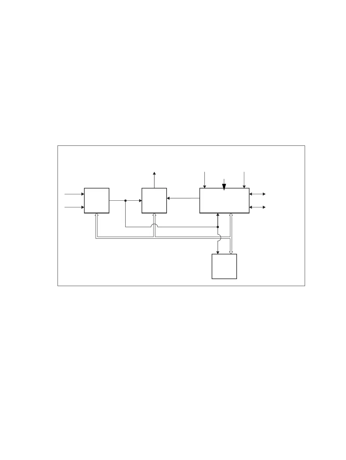
1.8 Theory of Operation
The reciter receives RF signals from its RF input (antenna), and outputs this
to the PA, along with a PA key signal. The reciter also receives signals
from, and sends signals to, the system interface, the Ethernet interface, and
the front panel (see Figure 1.5).
A system control bus interconnects the modules and carries alarm and
control signaling between the reciter and the other modules (refer to
“Intermodule Communications” on page 30 for more details).
The Ethernet interface carries VoIP and also allows maintainer access via
a web browser.
Figure 1.5 Base station high-level diagram
Reciter
PMU
PA
RF To
Antenna
RF From
Antenna
External
Reference
Frequency
AC Input
DC Input
28VDC
System Control Bus
RF + PA Key
System Input
and Output
Ethernet Interface
to Network
Front
Panel

 Loading...


