30 Description TB9300 Installation and Operation Manual
© Tait International Limited April 2024
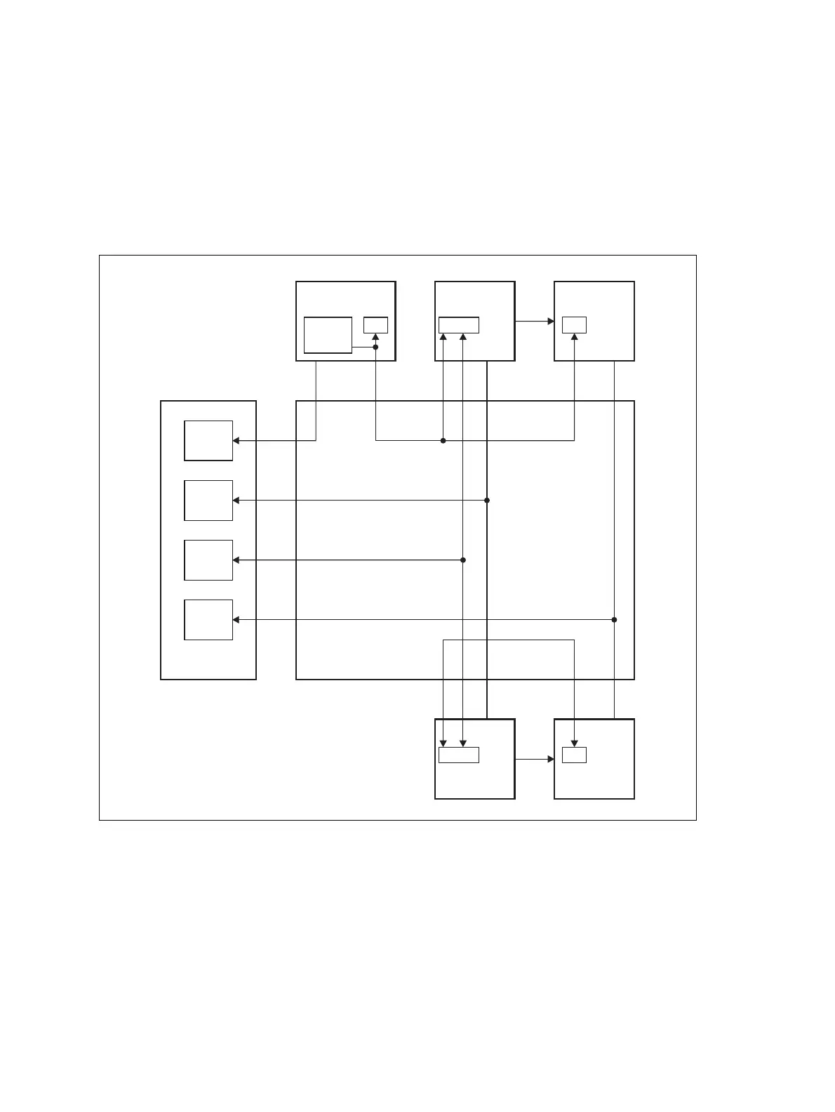
1.8.3 Intermodule Communications
A system control bus and a subrack interconnect board link the modules in
the subrack and carry alarm and control signaling between the reciter and
the other modules, as shown in Figure 1.8.
Specific configuration settings for dual base stations are described in
“Recommended Configuration Settings” on page 66.
Figure 1.8 Intermodule communication paths
FanFan
Fan
IC
2
IC
2
RS-485
RS-485
IC
2
IC
2
IC
2
Fan
Fan
Fan
PA 1
mP
Subrack Interconnect Board
PA 2
mP
Reciter 1
mP
Front Panel
Fan 3:
PMU
Fan 1:
Reciters
Fan 2:
PAs
Reciter 2
mP
User
Controls
PMU
mP
I C Current
Source
2

 Loading...


