82 Installation TB9300 Installation and Operation Manual
© Tait International Limited April 2024
4.6.4 Connecting the Auxiliary DC Power Output
The PMU can provide an auxiliary DC output from the auxiliary power
supply board. This board is available with an output of 13.65VDC,
27.3VDC, or 54.6VDC (depending on the model), and is current limited to
3A, 1.5A or 750mA respectively. The auxiliary power supply is
permanently on as soon as the base station has finished powering up, and
is available from the auxiliary output connector on the rear panel.
You can connect multiple auxiliary power supply boards in parallel for
redundancy purposes, or to provide an output greater than 40W. Although
no active current sharing is used, auxiliary boards connected in parallel will
current-share before reaching their power limit. The failure (or switching
off) of one auxiliary board will not load any other paralleled auxiliary
boards in the circuit.
The auxiliary power supply turns off briefly when the PMU restarts
after a firmware upgrade. This interruption may also cause any ancillary
equipment powered from the auxiliary supply to restart. If this is a prob-
lem for your system, we recommend connecting auxiliary power supply
boards in parallel to ensure an uninterrupted power supply for the ancil-
lary equipment.
Auxiliary DC Power
Output Cabling
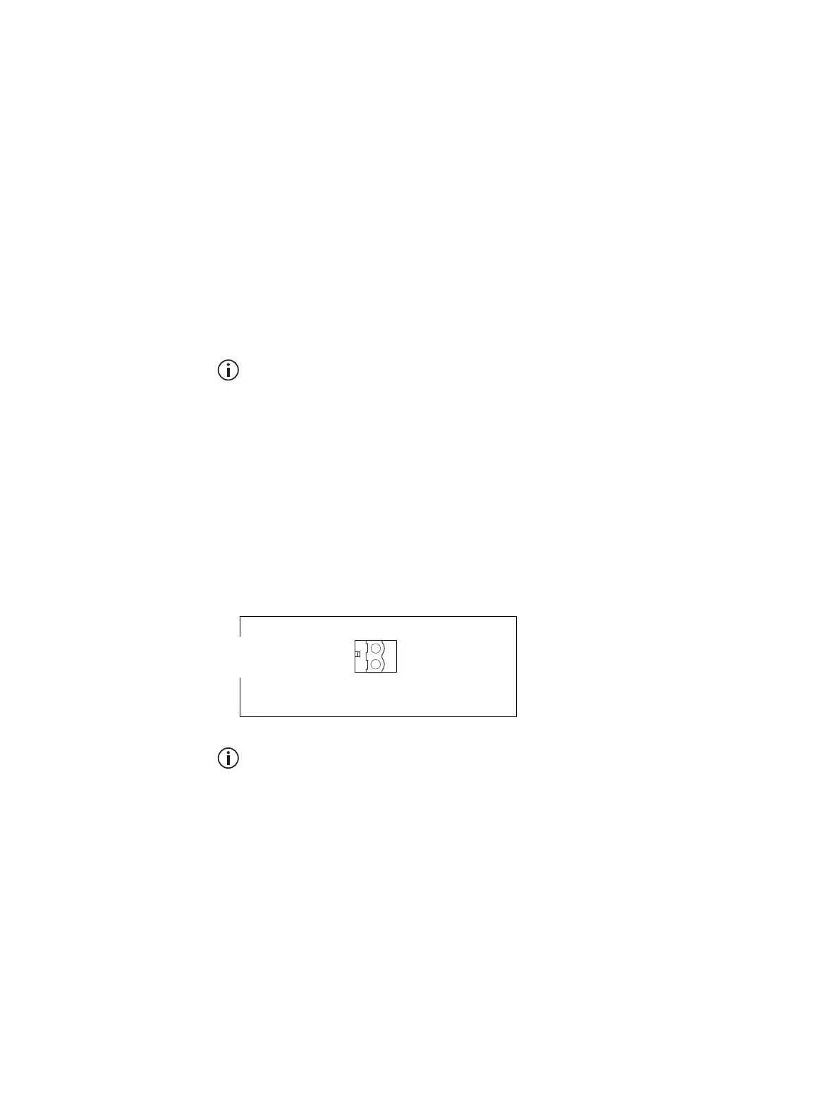
Network elements are supplied with a connector, as shown in Figure 4.10.
You can use this to connect the PMU’s auxiliary DC power output to
another device (refer to “PMU Auxiliary DC Output” on page 124 for the
pin allocations).
Note that on H/W version 4 PMUs, the auxiliary DC power connector
has been rotated 180
o
.
H/W Version 4
PMUs - Auxiliary
Voltage
On H/W version 4 PMUs, the auxiliary voltage is selected by moving a
jumper next to the output connector at the rear. The user can set the voltage
to 12 V, 24 V or 48 V.
Figure 4.10 Auxiliary DC power connector
Phoenix MVSTBR2.5HC/2-ST/5.08 female

 Loading...


