124 Appendix A Interface Pin Allocations TB9300 Installation and Operation Manual
© Tait International Limited April 2024
Appendix A Interface Pin Allocations
System Interface Connector
For the pin allocations for the system interface DB-25 connector, see
“Connecting General Purpose Inputs and Outputs” on page 87.
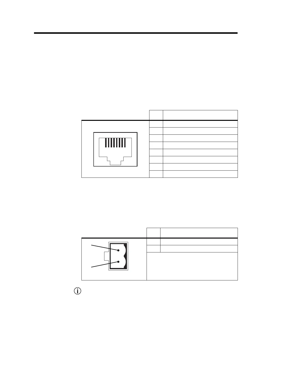
Ethernet Connector
PMU Auxiliary DC Output
The pin allocations for the auxiliary DC output on the PMU are given in the
following table.
Note that on H/W version 4 PMUs, the auxiliary DC power connector
has been rotated 180
o
.
Pin Description
1 transmit data +
2 transmit data –
3 receive data +
4 not connected
5 not connected
6 receive data –
7 not connected
8 not connected
Pin Description
1 -V output
2+V output
2-pin connector - external view
2
1

 Loading...


