TB9300 Installation and Operation Manual Replacing Modules 119
© Tait International Limited April 2024
18–20lbf·in (2–2.25N·m). Ensure the front panel cables are
positioned correctly, and retained where required by the cable
retaining clips in the top of the subrack (refer to “Appendix B Inter-
Module Connections” on page 125).
3. Carry out the instructions in “Final Reassembly” on page 121.
8.6 Replacing the Module Guide Rails
The module guide rails are held in place by four hooks that fit through the
slots in the top and bottom of the subrack. There is also a locking tab which
prevents the guide rails from working loose.
A subrack hardware spares kit (TBC-SP-002) is available, containing 5 top
and 5 bottom guide rails, blanking panels, clamps and screws.
Notice Subracks produced from late 2008 onwards have wider slots
than earlier subracks. Guide rails designed for these wider slots will not
fit older subracks with narrow slots.
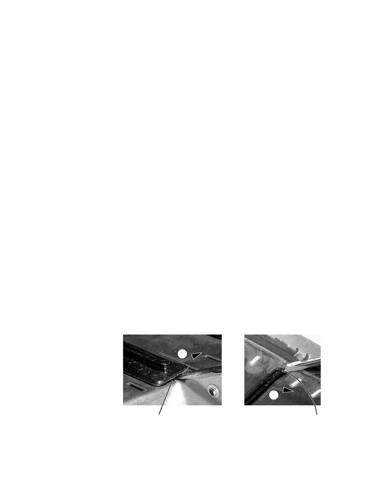
Removal 1. Bottom Guide Rails
a. Insert a small flat-blade screwdriver under the front end of the
guide rail and lift it slightly
b. This will ensure the small locking
tab is clear of the slot in the subrack.
b. While holding the front end of the guide rail up, pull the guide rail
towards the front of the subrack
c and lift it clear of the slots.
2. Top Rails
a. Insert a small flat-blade screwdriver under the rear end of the
guide rail and lift it slightly
d. This will ensure the small locking
tab is clear of the slot in the subrack.
b. While holding the rear end of the guide rail up, pull the guide rail
towards the rear of the subrack
e and lift it clear of the slots
.
bottom guide rail top guide rail
b
c
e
d

 Loading...


