TB9300 Installation and Operation Manual Operation 45
© Tait International Limited April 2024
3Operation
This section describes the user controls and indicator LEDs on the front
panel and on the base station modules.
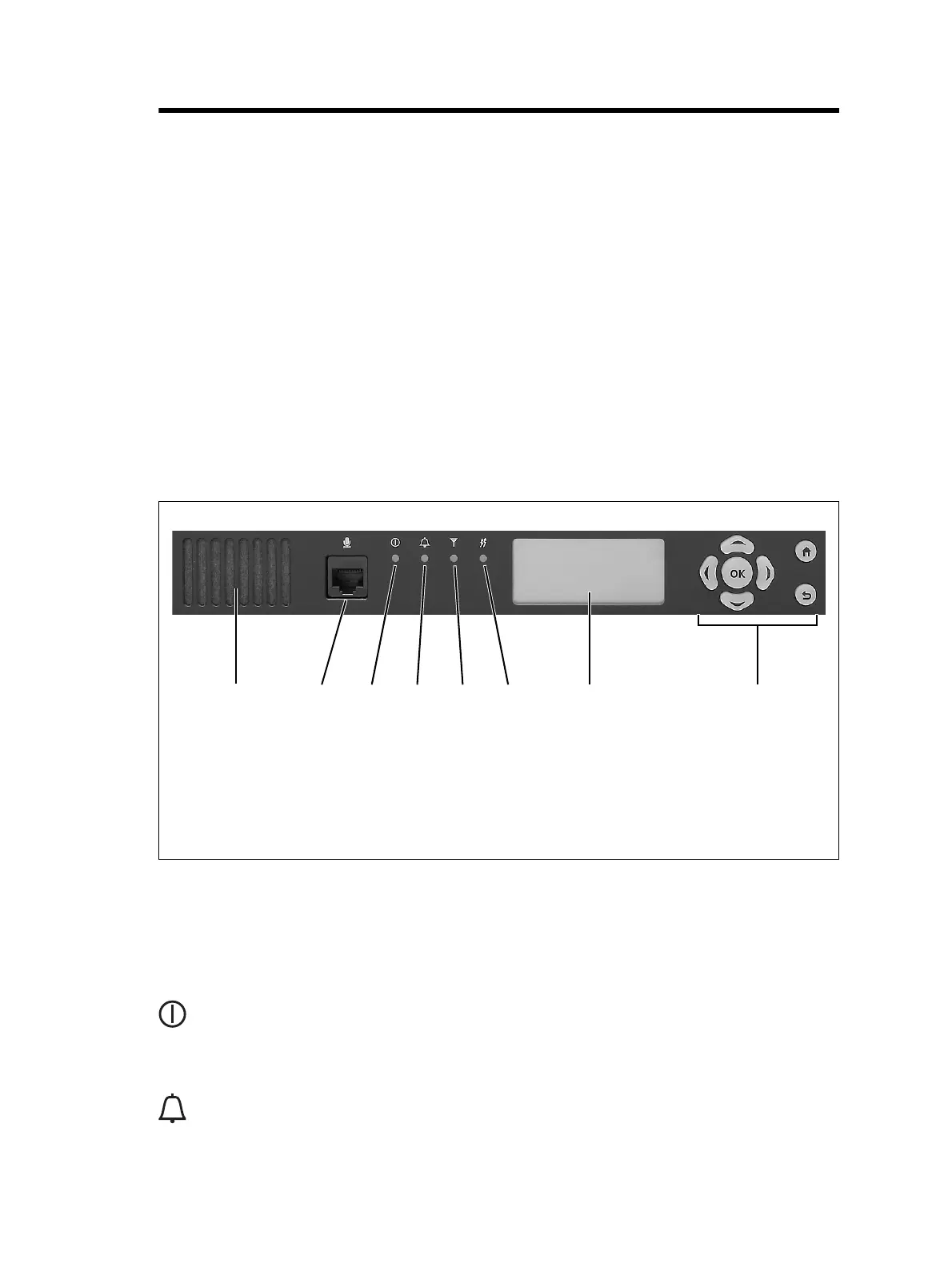
3.1 Front Panel
The user controls and indicator LEDs on the front panel are shown in
Figure 3.1. They allow some manual control over the base station and
monitoring of its operational status.
Notice If there is more than one reciter in a subrack, inputs from all
reciters are summed to drive the front panel LEDs.
Speaker and
Microphone
Connector
The speaker and microphone connector are not currently used.
Power LED The green power LED is lit when power is supplied to the subrack.
Alarm LED The red alarm LED will flash at a rate of 2 to 5Hz when an alarm has been
generated by any of the base station modules. It will continue to flash until
the alarm is canceled or the fault is fixed. Note that only those alarms that
are enabled using the WebUI will cause this LED to flash.
Figure 3.1 Operating controls on the control panel
b
speaker
f
receive LED
c
microphone connector
g
transmit LED
d
power LED
h
keypad
e
alarm LED
i
display

 Loading...


