20 Description TB9300 Installation and Operation Manual
© Tait International Limited April 2024
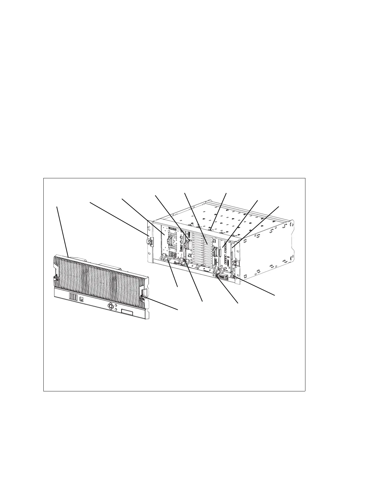
1.5 Mechanical Assembly
This section illustrates the main mechanical components of the base
station.
Figure 1.1 below shows the configuration for a typical dual 50W base
station. The subrack has six slots, numbered from right to left as viewed
from the front of the subrack. The PMU occupies slots 5 and 6, with the
reciters in slots 1 and 2. The two PAs are mounted vertically in slots 3 and
4 with the heatsinks facing each other. The airflow separator between the
PAs helps to direct the cooling airflow evenly through each heatsink. The
PMU and each pair of reciters and PAs have their own cooling fans.
The front panel can be easily removed from the subrack by undoing two
quick-release fasteners. Refer to “Replacing Modules” on page 113 for
more details.
.
Figure 1.1 Mechanical assembly - dual 50W base station with front panel
b front panel i reciter 1
c subrack j module retaining clamp
d PMU 1) subrack interconnect board
e PA 2 1! plastic guide rail
f PA 1 1@ subrack interconnect board retaining clamp
g cable retaining clip 1# front panel fastener
h reciter 2

 Loading...


