232 Frequency Synthesizer Fault Finding TM8100/TM8200 Service Manual
© Tait Electronics Limited June 2006
Task 36 —
TCXO Output
If the VCXO output is correct, check the TCXO output as follows:
1. Use the oscilloscope probe to check the TCXO output at the
TP504
test point (see Figure 9.17). The signal is
SYN RX OSC and should be:
2. If the signal is correct, go to “Signals at TP501 and TP502” on
page 233. If it is not, go to Step 3.
3. The TCXO circuitry under the
CDC TOP can is faulty. Remove the
CDC TOP can.
4. Locate and repair the fault in the TCXO (XL500 and associated
components) (see Figure 9.16).
5. Confirm the removal of the fault and go to “Signals at TP501 and
TP502” on page 233. If the repair failed, replace the board and go to
“Final Tasks” on page 157.
TCXO output at TP504 test point: clipped sine wave of 1.0 ± 0.2 V
pp
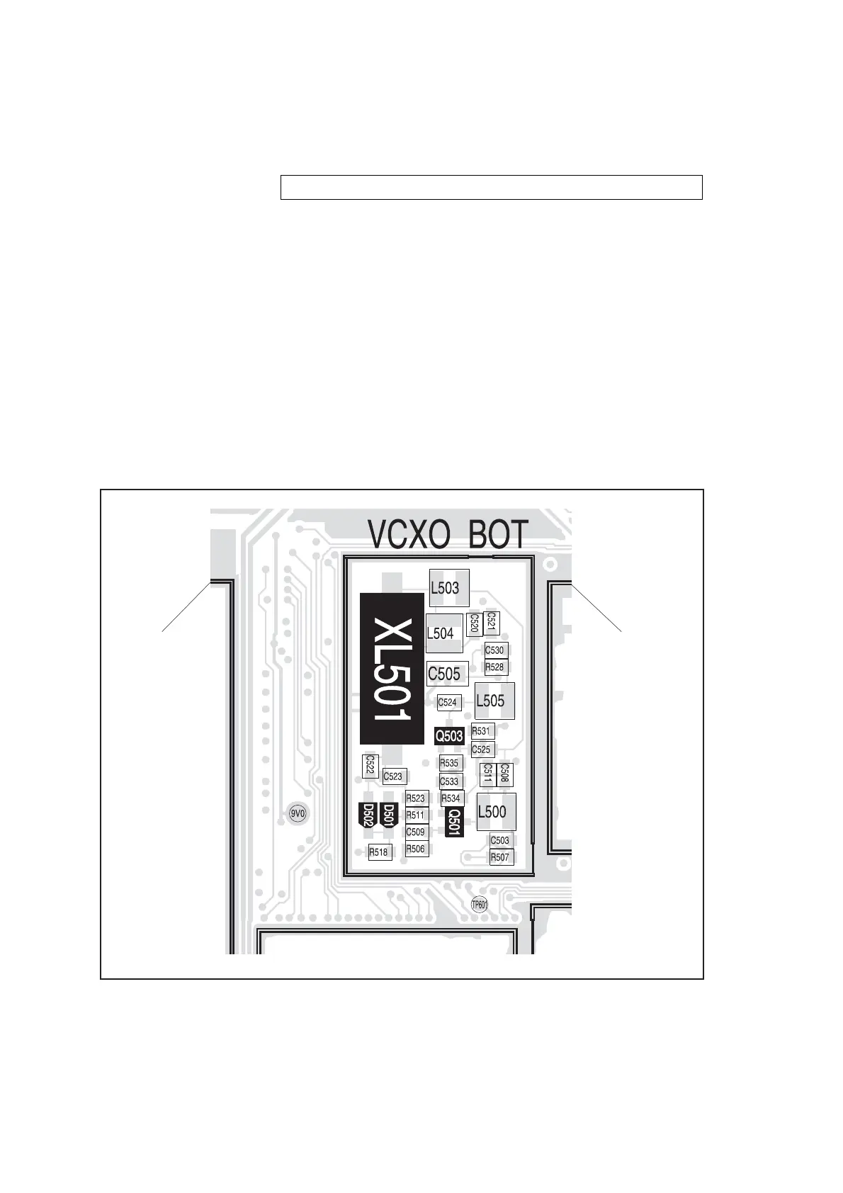
Figure 9.18 FCL circuitry under the VCXO BOT can
SYN BOT CAN
CDC BOT CAN
CAN FOR
DIGITAL
BOARD
 Loading...


