TM8100/TM8200 Service Manual CODEC and Audio Fault Finding 383
© Tait Electronics Limited June 2006
Task 3 —
2.5V Power Supply
If the 9V and 3V supplies are correct, the remaining power supply to check
is the 2.5V DC supply (+2
V5 CDC).
1. Measure the voltage +2
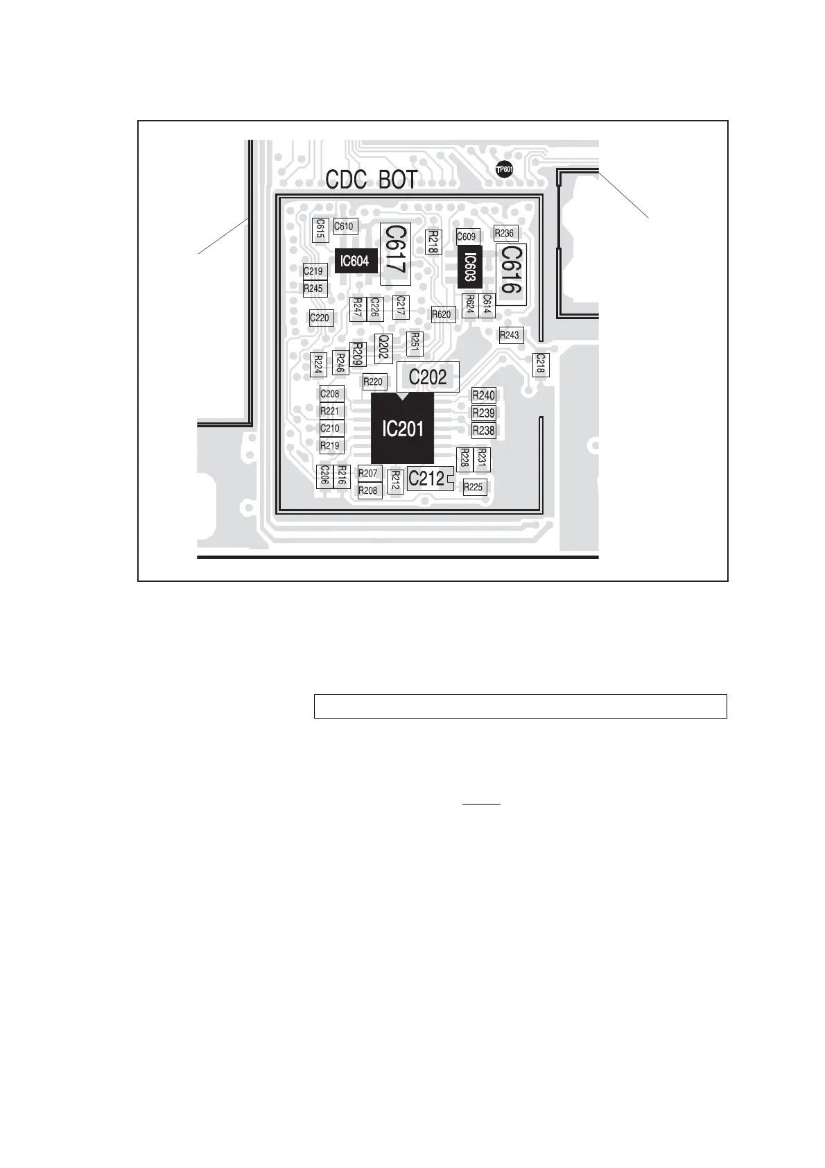
V5 CDC at pin 5 of IC604 (see Figure 13.1).
2. If the voltage is correct, go to Step 4. If it is not, go to Step 3.
3. The 2.5V regulator IC604 is suspect (see Figure 13.1). Check the
regulator as described in Tas k 3
of “Power Supply Fault Finding” on
page 168.
4. Proceed to the section relevant to the fault exhibited:
■ “Faulty Speaker Audio” (distorted or no speaker audio)
■ “No Speaker Audio at Auxiliary Connector” (no speaker audio at
auxiliary connector)
■ “Faulty Receiver” (receiver does not operate)
■ “Faulty Modulation” (distorted or no transmit modulation)
■ “Faulty Modulation Using Auxiliary Connector” (modulation at
auxiliary connector only)
Further details are given in the introduction to the section.
Figure 13.1 Power-supply circuitry for the CODEC and audio circuitry under the CDC BOT can
LO2 BOT CAN
CAN FOR
DIGITAL
BOARD
pin 5 of IC604: 2.5 ± 0.3V DC
 Loading...


