Operating Information
TLA5000 Series Service Manual
2-7
Operating Information
All features of the logic analyzer can be accessed thr ough the menus using a
mouse. Refer to the online help for specific operating information.
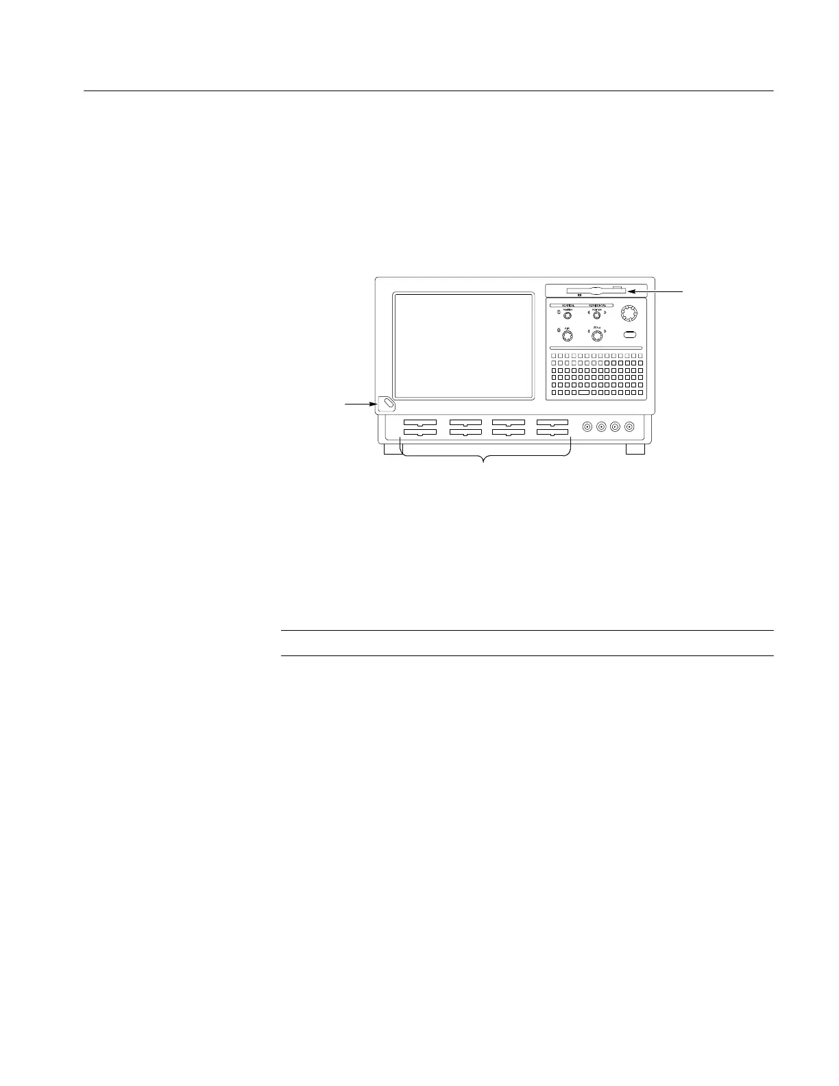
Figure 2--5 shows the controls, connectors and floppy disk drive location.
Floppy
disk drive
Probe Connectors
On/Standby
switch
Figure 2- 5: Controls and connectors on the front panel
The multi-function knob is used primarily for incrementing and decrementing
values in selected menu boxes. The four positioning and scale knobs provide
scrolling of the logic analyzer displays.
NOTE. For external connectors on the rear panel see Figure 2--2 on page 2--3.
Connecting Probes to the Target System
The logic analyzer connects to the target system through probes. Several
different probes are available for the logic analyzer. For probe-specific connec-
tion details, refer to the appropriate probe instruction manual or browse the
Tektronix Web site.
Additional Information
For detailed information on using the logic analyzer refer to the online help. F or
additional information on the latest software version or other information, refer
to the release notes. To access the release notes, click Start > Programs >
Tektronix Logic Analyzer > TLA Release Notes.

 Loading...


