Performance Verification
TLA5000 Series Service Manual
4-11
Performance Verification Procedures
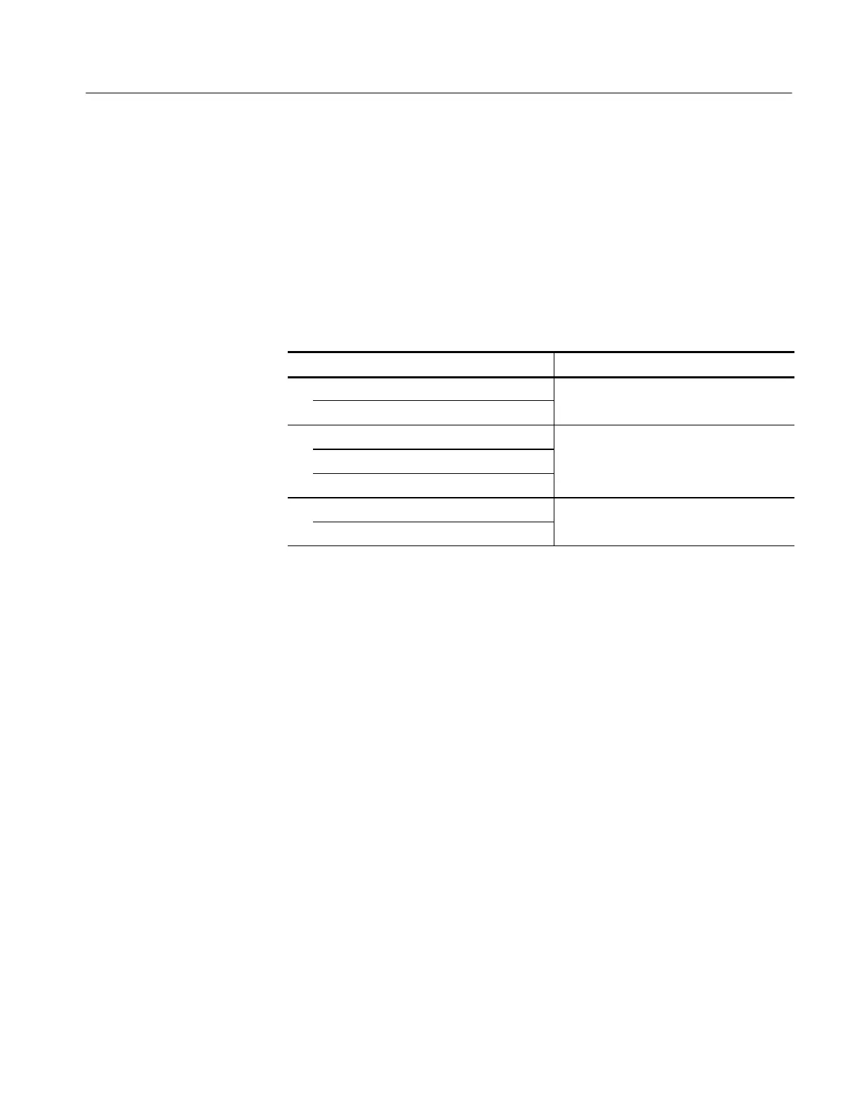
Table 4--3 provides a summary of the performance verification procedures. The
procedures are listed by groups and include individual procedures. Some of these
procedures are optional and are recommended for performing a thorough
performance verification. Others are the minimum required to verify the
advertised specifications of the logic analyzer. Each group requires different
equipment setups.
Table 4- 3: TLA5000 performance verification procedures
Procedure by groups Notes
Module+Probe Gain and Offset Procedures
Threshold
1
Module+Probe Timing Procedures
Pulse Width
Timebase
2
Setup and Hold Procedure Can only be verified with P419 logic
Setup and Hold
n
l
zer probes
1
Certifiable parameter. This procedure can be run separate from the performance
verification procedures. Select the Certification button from main window in the
software. The Certification instructions are listed on page 4- 19.
2
The Timebase procedure indirectly tests the CLK10 specification.
Use the tables and illustrations to set up and execute the procedures. The
procedures assume that you have already installed the performance verification
software on the logic analyzer. They also assume that you will only perform the
procedures selected in each group.
Figure 4--3 shows the locations of connectors and test points on the test fixture.
You may need to refer to this illustration when connecting probes to the test
fixture. You should also refer to the label on top of the test fixture.

 Loading...


