Removal and Installation Procedures
6-20
TLA5000 Series Service Manual
c. Align the holes in the flex circuit to the two index posts on the front side
of the Display assembly.
d. Firmly press the flex circuit to the Display assembly chassis surface.
7. Reinstall the display assembly and then the trim and covers.
Front-Panel Knobs
1. Set the instrument so its bottom is down on the work surface and its front is
facing you.
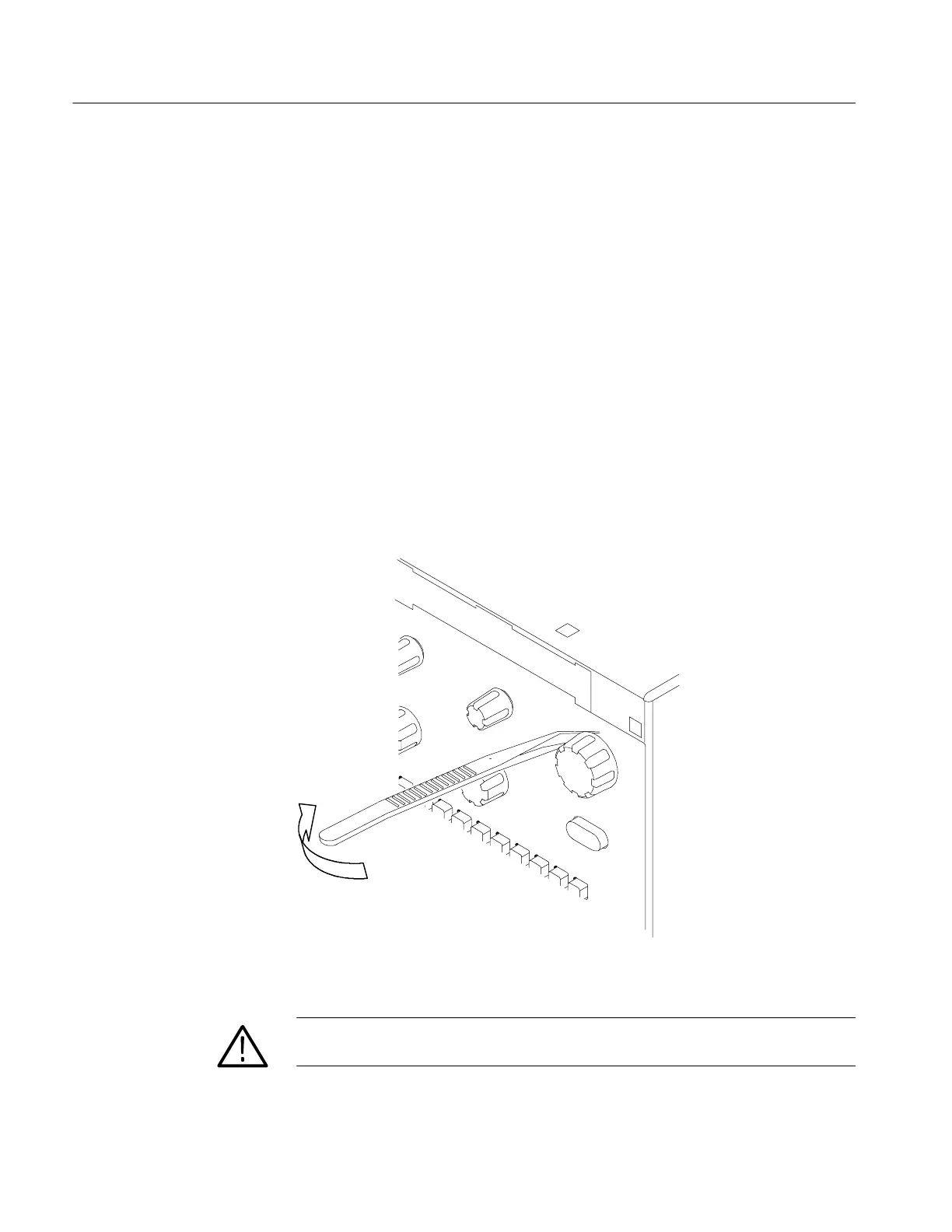
2. Remove the knob(s): Grasp any knob you want to remove and pull it straight
out from the front panel
1
@
4
inch to create some clearance between the base of
the knob and the front panel. Insert the angled-tip tweezers between the knob
and front panel and use them to remove the knob. S ee Figure 6--9.
Figure 6- 9: Knob removal
CAUTION. To prevent damage to the encoders located onto the cir cuit board,
apply pressure to the encoders while pushing the knob on the shaft.
3. To reinstall the knob, align the knob to the shaft and push it in until it snaps.

 Loading...


