Removal and Installation Procedures
TLA5000 Series Service Manual
6-19
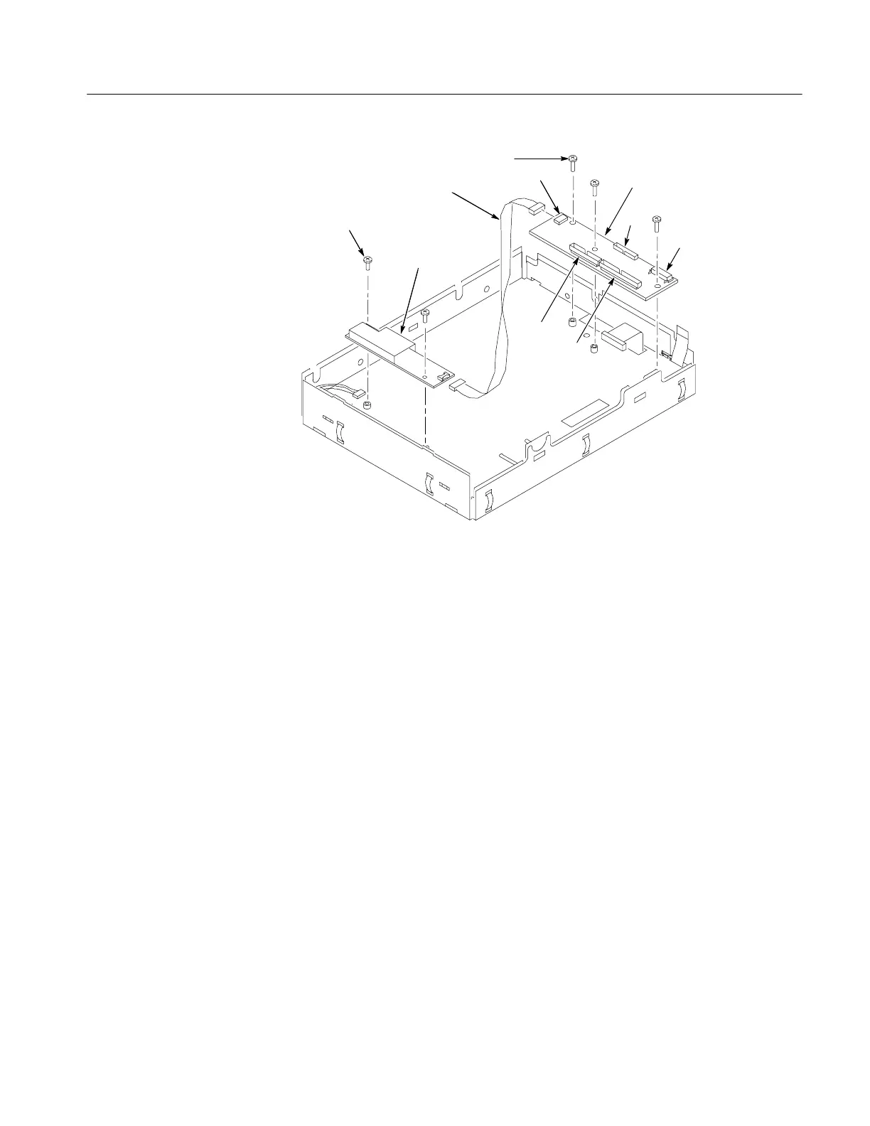
Display adapter board
Inverter board
T-15 Torx-drive
screws (3)
Screws (2)
J7
J4
J2
J3
J5
Inverter Adapter cable
Figure 6- 8: Display adapter board removal
Standby/On Switch Flex Circuit
1. Remove the trim and covers by following the procedure on page 6--7.
2. Remove the display assembly by following the procedure on page 6--17.
3. Peel the Standby/On switch flex circuit away from the front of the display
assembly.
4. Disconnect the flex circuit from the Display Adapter circuit board.
5. Grasp the flex circuit and pull it out of the Display assembly.
6. To reinstall the Standby/On Switch.
a. Remove the protective backing on the new Standby/On switch flex
circuit.
b. Slide the connector end of the Standby/On switch flex circuit through the
slot in the Display assembly. Make sure the flex circuit connector aligns
to the connector on the Display Adapter circuit board.

 Loading...


