Performance Verification
4-18
TLA5000 Series Service Manual
6. Click the Next button at the bottom of the dialog box to display the probe
connection instructions. Follow the on-screen instructions to connect the
probes from the logic analyzer to the test fixture. If necessary, refer
Figure 4--6 on page 4--6 and to the test fixture label to determine the correct
probe connection.
NOTE. When connecting the P6419 Logic Analyzer probes, make sure that the
alignment pin on the probe head aligns w ith the hole on the test fixture. Tighten
the probe head screws by alternating between them until they are finger tight (no
more than 1 in-lbs of torque).
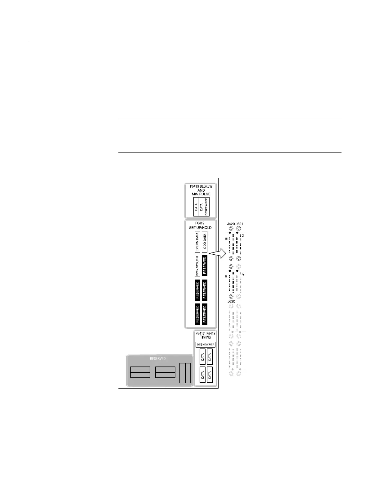
Figure 4- 6: P6419 Setup & Hold procedure connections
7. Click the Next button at the bottom of the dialog box to begin the procedure.

 Loading...


