PLLX Lock Count
PLLX_DLD_CNT
=
Phase Error < g
NO
NO
NO
YES
Phase Error < g
START
PLLX
Lock Detected = False
Lock Count = 0
Increment
PLLX Lock Count
PLLX
Lock Detected = True
YES
YES
LMK04821
,
LMK04826
,
LMK04828
www.ti.com
SNAS605AR –MARCH 2013–REVISED DECEMBER 2015
9.3.5.3 Input Clock Switching - Automatic Mode
When CLKin_SEL_MODE is 4, the active clock is selected in round-robin order of enabled clock inputs starting
upon an input clock switch event. The switching order of the clocks is CLKin0 → CLKin1 → CLKin2 → CLKin0,
and so forth.
For a clock input to be eligible to be switched through, it must be enabled using EN_CLKinX.
Starting Active Clock
Upon programming this mode, the currently active clock remains active if PLL1 lock detect is high. To ensure a
particular clock input is the active clock when starting this mode, program CLKin_SEL_MODE to the manual
mode which selects the desired clock input (CLKin0, 1, or 2). Wait for PLL1 to lock PLL1_DLD = 1, then select
this mode with CLKin_SEL_MODE = 4.
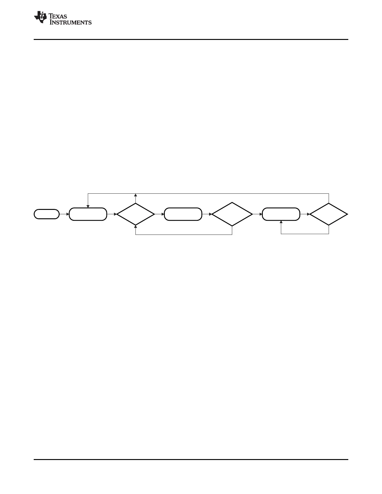
9.3.6 Digital Lock Detect
Both PLL1 and PLL2 support digital lock detect. Digital lock detect compares the phase between the reference
path (R) and the feedback path (N) of the PLL. When the time error, which is phase error, between the two
signals is less than a specified window size (ε) a lock detect count increments. When the lock detect count
reaches a user specified value, PLL1_DLD_CNT or PLL2_DLD_CNT, lock detect is asserted true. Once digital
lock detect is true, a single phase comparison outside the specified window will cause digital lock detect to be
asserted false. This is illustrated in Figure 16 .
Figure 16. Digital Lock Detect Flowchart
This incremental lock detect count feature functions as a digital filter to ensure that lock detect isn't asserted for
only a brief time when the phases of R and N are within the specified tolerance for only a brief time during initial
phase lock.
See Digital Lock Detect Frequency Accuracy for more detailed information on programming the registers to
achieve a specified frequency accuracy in ppm with lock detect.
The digital lock detect signal can be monitored on the Status_LD1 or Status_LD2 pin. The pin may be
programmed to output the status of lock detect for PLL1, PLL2, or both PLL1 and PLL2.
9.3.6.1 Calculating Digital Lock Detect Frequency Accuracy
See Digital Lock Detect Frequency Accuracy for more detailed information on programming the registers to
achieve a specified frequency accuracy in ppm with lock detect.
The digital lock detect feature can also be used with holdover to automatically exit holdover mode. See Exiting
Holdover for more info.
Copyright © 2013–2015, Texas Instruments Incorporated Submit Documentation Feedback 43
Product Folder Links: LMK04821 LMK04826 LMK04828
 Loading...


