HYDRAULIC SYSTEM
6-53TX525 Service Manual Rev. 000
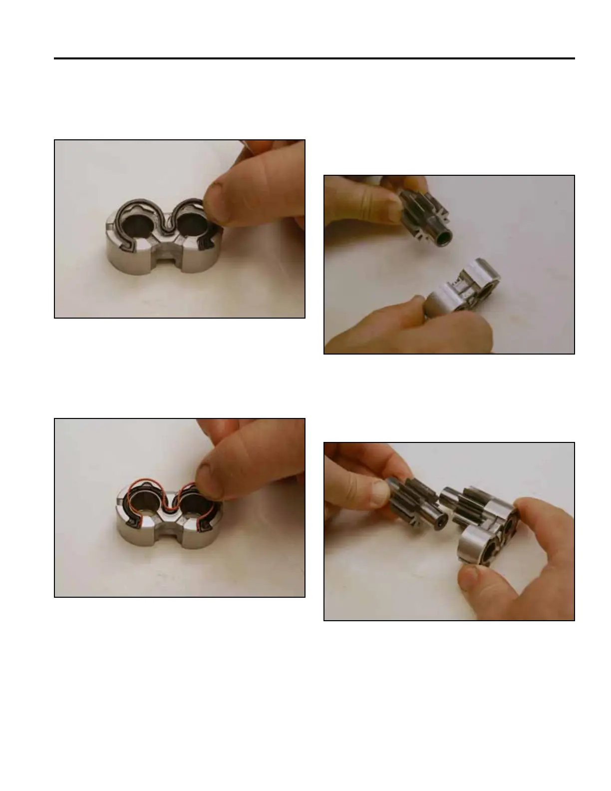
8. Install the gear seal with the lip side of the gasket
facing away from the groove of the bushing (Fig.
1030).
10. Repeat the above 2 steps for the second bushing,
gear seal and back-up ring.
11. Making note of the markings on the bushing as-
sembly, install the drive gear into the bushing (Fig.
1032).
Fig 1030 PICT-2877a
Fig 1032 PICT-2879a
12. Install the driven gear onto the bushing (Fig. 1033).
9. Install the back-up ring into the bushing so that it
rests in the lip of the gear seal (Fig. 1031).
Fig 1033 PICT-2880a
Fig 1031 PICT-2878a

 Loading...


