BRAKES
8-41TX525 Service Manual Rev. 000
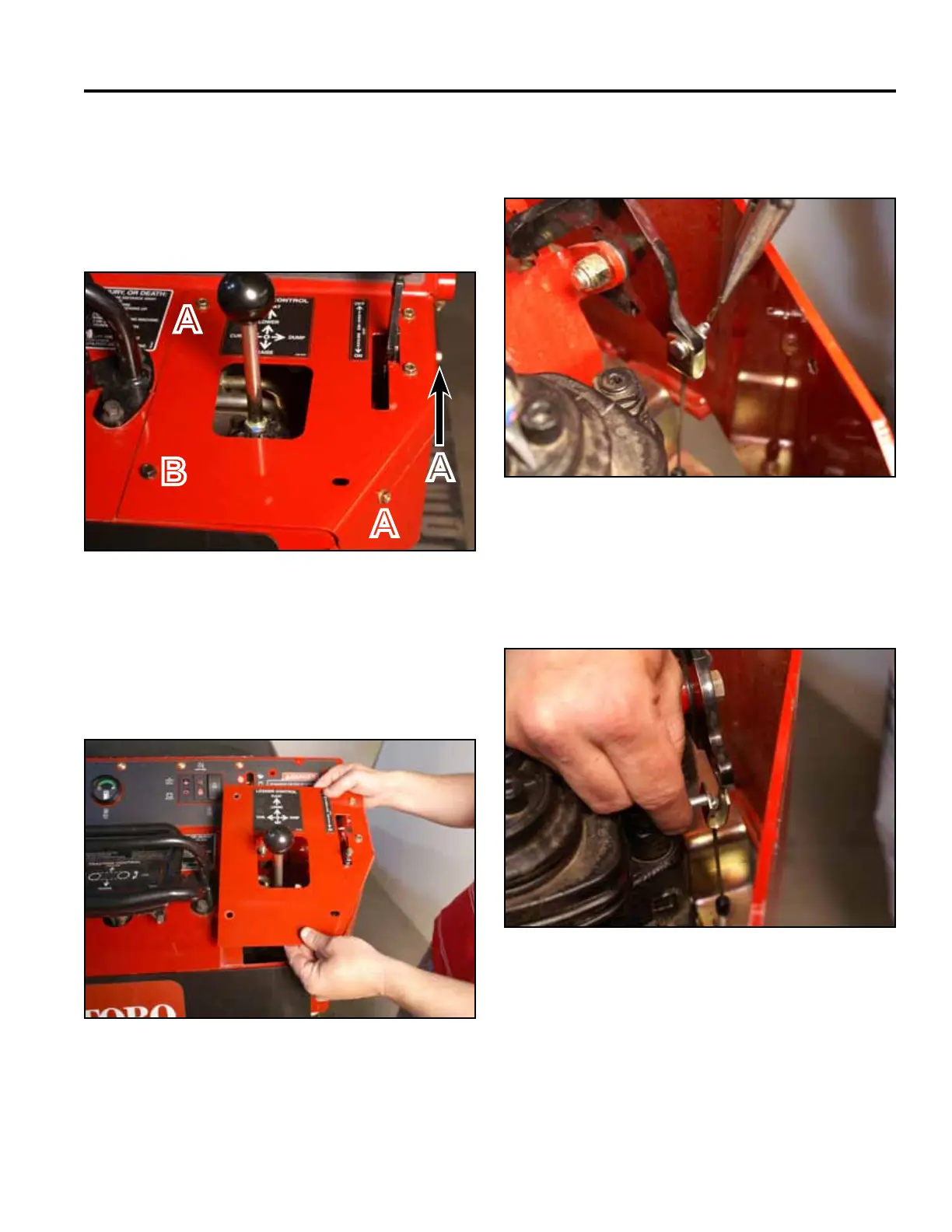
4. Using a 3/8” socket, remove the 3 self-tapping
screws that secure the top right panel to the control
panel assembly. Using a 3/8” socket and a 7/16”
socket, remove the bolt and nut securing the lower
left corner of the top right panel to the control panel
assembly (Fig. 1785).
6. Remove the cotter pin from the clevis pin attaching
the brake cable to the brake handle (Fig. 1787).
Fig 1785 PICT-4341
Fig 1787 PICT-4345
7. Support the brake handle and remove the clevis pin
that retains the brake cable to the brake handle (Fig.
1788).
5. Remove the right panel from the control panel
assembly (Fig. 1786).
A. Self-tapping screw (3) B. Bolt and nut
Fig 1788 PICT-4347
Fig 1786 PICT-4343a
A
B
A
A

 Loading...


