Error! Style not defined. Error! Style not defined. 4 Replacement Procedures
4.1 General
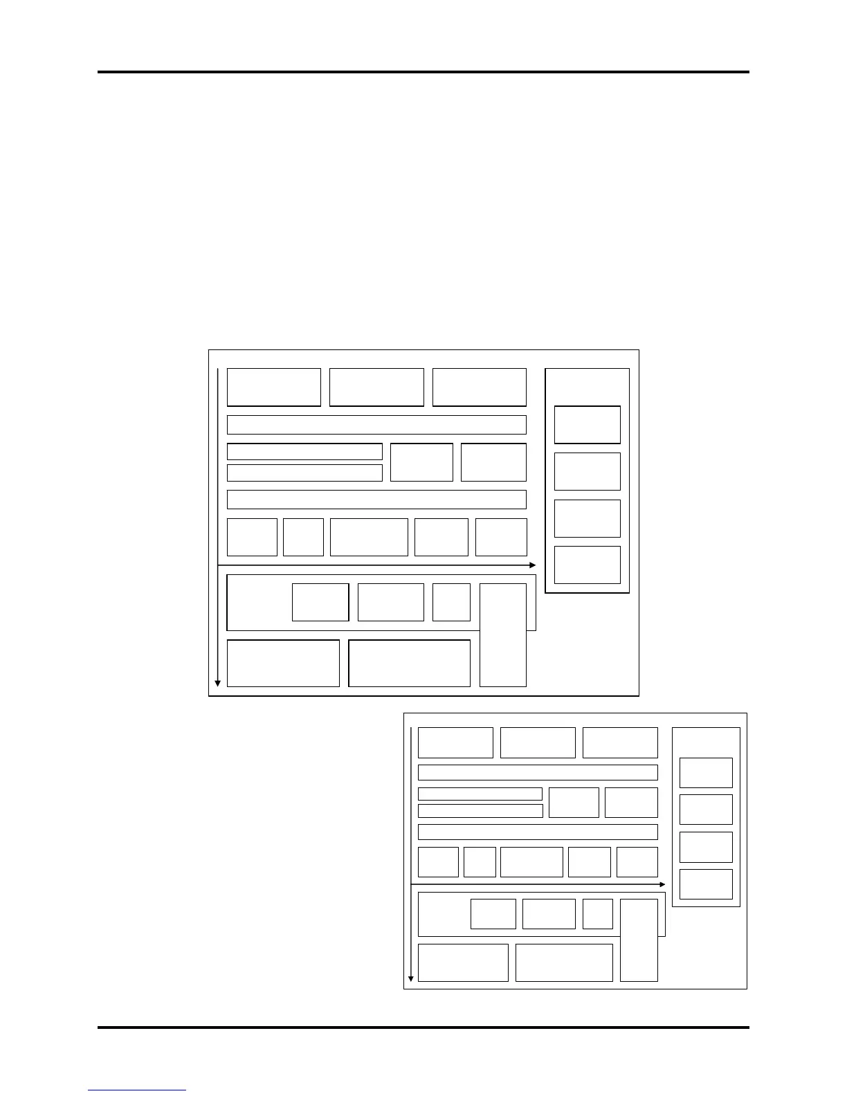
This chapter explains how to disassemble the computer and replace Field Replaceable Units
(FRUs). Some replacement procedures may not require you to remove all the surrounding FRUs
to replace only one FRU. The chart below shows the FRUs in the order in which they should be
removed in a top-down manner, irrespective of their physical locations. The FRUs shown in the
top area of the chart should normally be removed before removing the FRUs shown in the
bottom area. To replace the FRUs, first identify the suspect FRU for the system failure. Next,
according to this chart, determine the FRUs that need to be removed before removing the suspect
FRU. After you determine those FRUs, go to the appropriate sections according to the section
numbers shown in the boxes. Then start removal and replacement.
4.2
Battery
4.3
HDD
4.4
Memory
4.5 Keyboard Cover & Keyboard
4.8 Express
Dummy Card
4.6 Wireless LAN Card and UWB Card
4.7 ODD
4.10 Top Cover
4.12 DC-in
jack
4.14 Touch Pad &
Finger Print Board
4.15 Power
Switch
4.16 Audio
Card
4.17 MDC
Module &
System Board
4.18 VGA
Module
4.19 Cooling
Module & Fan
4.11
Display Assembly
4.20
CPU
4.24
Display Mask
4.25 FL
Inverter Board
4.26
CCD & MIC
4.27 LCD
Modules
4.21
Sub-speakers
& Sub-woofer
4.22
Bluetooth, Wi-Fi, Touch Pad
LED Board
4.23
Bridge
Media &
FM
Radio
4.9 Optional
Memory Card
4.13
Speaker
How to use the chart (two examples):
4.2
Battery
4.3
HDD
4.4
Memory
Qosmio X300 Maintenance Manual 4-1
• For removing the System Board:
First, remove the top cover with the
display assembly. Then, remove the
HDD, selectable bay module, Bluetooth
card, keyboard, and wireless LAN card,
all of which are shown above the top
cover with the display assembly.
• For removing the LCD Module:
First, remove the display mask and FL
inverter board, both of which are shown
above the LCD module.
4.5 Keyboard Cover & Keyboard
4.8 Express
Dummy Card
4.6 Wireless LAN Card and UWB Card
4.7 ODD
4.10 Top Cover
4.12 DC-in
jack
4.14 Touch Pad &
Finger Print Board
4.15 Power
Switch
4.16 Audio
Card
4.17 MDC
Module &
System Board
4.18 VGA
Module
4.19 Cooling
Module & Fan
4.11
Display Assembly
4.20
CPU
4.24
Display Mask
4.25 FL
Inverter Board
4.26
CCD & MIC
4.27 LCD
Modules
4.21
Sub-speakers
& Sub-woofer
4.22
Bluetooth, Wi-Fi, Touch Pad
LED Board
4.23
Bridge
Media &
FM
Radio
4.9 Optional
Memory Card
4.13
Speaker
 Loading...