18 Installation and maintenance instructions 0020308118_05
– Seasonal weather effects
– Various tolerances of unit-internal components
The values can be read in the following time forms:
– Today
– Yesterday
– Last month
– Last year
– Total
The recording of the values only includes the product in the
factory-delivered condition. Supplementary accessories,
even if they are installed on the product, as well as any other
components in the heating system and other external con-
sumers, are not part of the data recording.
Deviations between the determined values and the actual
values may be significant. The determined values are there-
fore not suitable for creating or comparing energy billing, for
example.
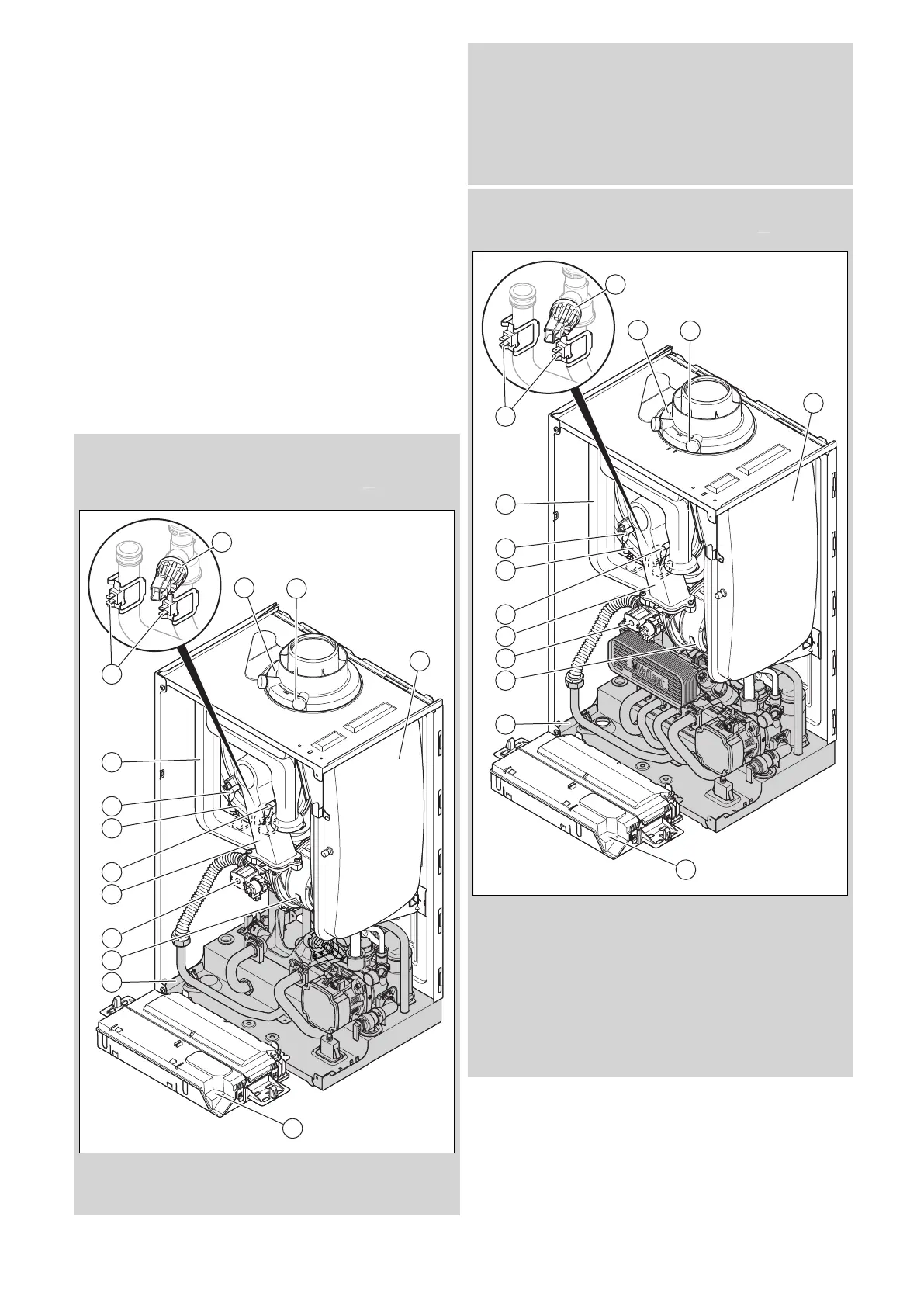
5.9 Product design
Validity: VU 10CS/1-5 (N-GB) ecoTEC plus 610 OR VU 15CS/1-5 (N-
GB) ecoTEC plus 615 OR VU 20CS/1-5 (N-GB) ecoTEC plus 620 OR
VU 25CS/1-5 (N-GB) ecoTEC plus 625 OR VU 30CS/1-5 (N-GB) ecoTEC
plus 630 OR VU 35CS/1-5 (N-GB) ecoTEC plus 635
1 Connection for the
air/flue pipe
2 Flue gas analysis point
3 Expansion vessel
4 Electronics box
5 Hydraulic block
6 Fan
7 Gas valve assembly
8 Compact thermal
module
9 Control electrode
10 Heat exchanger
11 Ignition electrode
12 Air intake pipe
13 Temperature sensor
14 Water pressure sensor
Validity: VUW 20/26CS/1-5 (N-GB) ecoTEC plus 826 OR VUW 25/32CS/1-
5 (N-GB) ecoTEC plus 832 OR VUW 30/36CS/1-5 (N-GB) ecoTEC plus 836
OR VUW 30/40CS/1-5 (N-GB) ecoTEC plus 840
1 Connection for the
air/flue pipe
2 Flue gas analysis point
3 Expansion vessel
4 Electronics box
5 Hydraulic block
6 Fan
7 Gas valve assembly
8 Compact thermal
module
9 Control electrode
10 Heat exchanger
11 Ignition electrode
12 Air intake pipe
13 Temperature sensor
14 Water pressure sensor
 Loading...


