52 Installation and maintenance instructions 0020308118_05
Validity: VU 35CS/1-5 (N-GB) ecoTEC plus 635 OR VUW 30/40CS/1-5 (N-
GB) ecoTEC plus 840
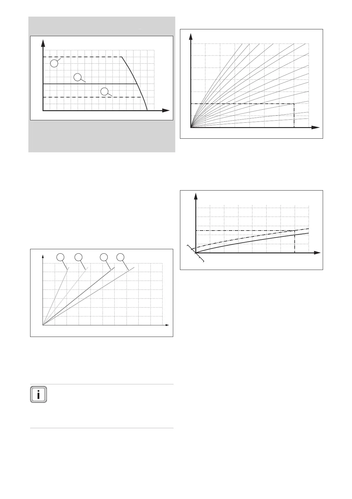
400
300
200
100
0
600200 400 800 1000 1400 16001200
B
A
2
3
1
A Pressure [mbar]
1 Minimum pressure
2 Maximum pressure
B Flow rate [l/h]
3 Factory setting
Underfloor heating
Direct supply is only possible via the internal heating pump.
However, carefully check the potential of the internal heating
pump.
Underfloor heating systems are heating surfaces with a low
spread and, therefore, a high demand for cycles. The lar-
ger the cycle, the higher the pressure loss. The potential of
the internal heating pump for such systems is limited. If the
potential of the internal heating pump is not sufficient, the
heat generator must be decoupled from the heating surfaces
(e.g. using a low loss header, heat exchanger, buffer cylin-
der, etc.). Beyond the decoupling, an external heating pump
can be designed exactly for the application.
0 2 4 6 8 10 12 14 16 18 20
B
400
600
800
1000
1200
1400
200
0
A
1 2 3 4
A Potential heating sys-
tem cycles [l/h]
B Maximum heat output
of underfloor heating
systems [kW]
1 3 K system
2 5 K system
3 8 K system
4 10 K system
Note
The diagram is only used as a rough guide. It
does not replace planning. Furthermore, there is
no functional warranty for a heating system, since
each heating system is individual and requires
planning.
10.3.8 Setting the heat curve
A
B
15 10 5 0 -5 -10 -15 -20
20
30
40
50
60
70
80
90
1.2
1.5
1.822.533.54
0.8
1.0
0.4
0.2
0.1
0.6
A Outdoor temperature °C B Target flow temperature
°C
The figure shows the possible heat curves of 0.1 to 4.0 for a
target room temperature of 20 °C. If, for example, heat curve
0.4 is selected, a flow temperature of 40 °C is maintained at
an outdoor temperature of -15 °C.
A
B
CD
18
22
20
0.4
70
60
50
40
30
15 10 5 0 -5 -10 -15 -20
A Outdoor temperature °C
B Target flow temperature
°C
C Target room temperat-
ure °C
D Axis a
If the heat curve 0.4 is selected and 21 °C is specified for the
target room temperature, the heat curve is then translated,
as shown in the figure. The heat curve is displaced accord-
ing to the value of the target room temperature along axis a
which is angled at 45°. At an outdoor temperature of -15 °C,
the control system provides a flow temperature of 45 °C.
▶ Navigate to MENU → SETTINGS → Installer level → In-
stallation configuration → Heating → Heat curve:.
▶ Use the scroll bar to select the required value.
▶ Exit the menu level. (→ Section 8.8)
 Loading...


