0020308118_05 Installation and maintenance instructions 63
13.7.7 Replacing the gas valve assembly
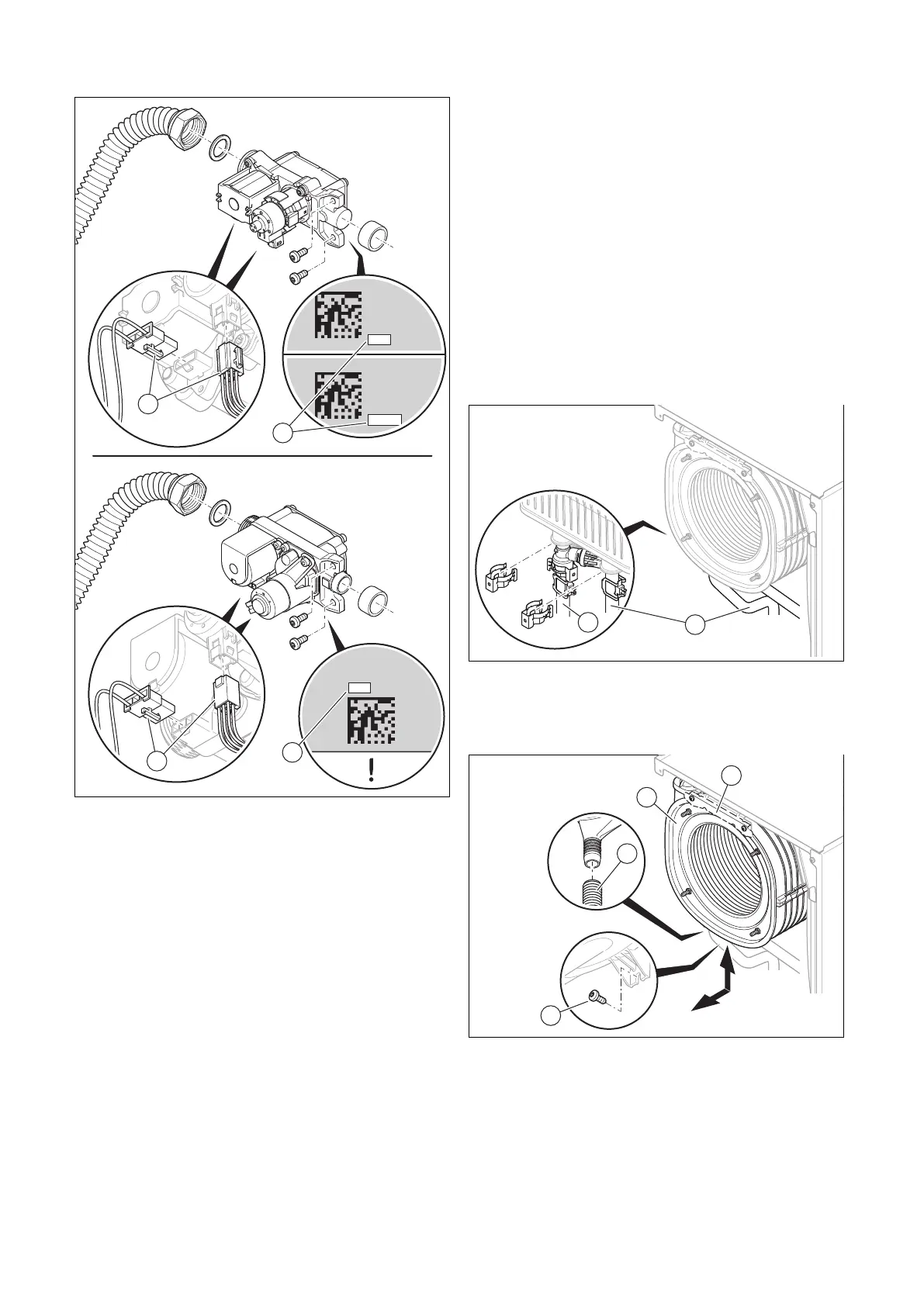
Removing the gas valve assembly
xxxxxx
xxxxxxxxxx
xxxxxx
xxxxxxxx
xxxxx
xxxxxx
xxxxxxxxxx
xxxxxx
xxxxxxxx
xxx
xxxxxxxxxx
xxxxxx
xxxxxxxx
xxx
1. Remove the two plugs (2) from the gas valve
assembly.
2. Unscrew the union nut from the gas valve assembly.
3. Unscrew two screws to secure the gas valve assembly
to the fan.
4. Remove the gas valve assembly.
5. Read the offset (1) that is printed on the rear (type A)
or underside (type B) of the new gas valve assembly
and note this down.
Installing the gas valve assembly
6. Insert the gas valve assembly. When doing so, replace
all of the seals.
7. Use both screws to fasten the gas valve assembly onto
the fan.
8. Screw the union nut onto the gas valve assembly with
a new seal. In the process, secure the gas pipe against
twisting. Tightening torque, see appendix.
9. Plug in both of the gas valve assembly's plugs.
10. Check the gas valve assembly and the connections for
tightness. (→ Section 9.17)
11. Install the front casing. (→ Section 7.11)
12. If the offset that you read has five digits, set dia-
gnostics code D.052 using the first three digits.
(→ Section 8.3)
13. If the offset that you read has three digits, set
diagnostics code D.052. (→ Section 8.3)
14. If the product is set with liquefied petroleum gas as the
gas type and the offset that you read has five digits,
set diagnostics code D.182 using the last two digits.
(→ Section 8.3)
15. Exit the menu level. (→ Section 8.8)
16. Check the O₂ content. (→ Section 9.13.4)
13.7.8 Replacing the heat exchanger
1. Remove the connector for the air/flue pipe.
(→ Section 7.2.6.1)
2. Remove the side casing. (→ Section 13.7.2)
3. Remove the compact thermal module.
(→ Section 12.7.1)
4. Remove the clips from the flow pipe (2) and the return
pipe (1).
5. Loosen the pipes for the flow/return on the heat ex-
changer.
6. Remove the condensate discharge hose (4) from the
heat exchanger (1).
7. If a front retainer (2) is available, remove the two
screws from the retainer and remove the retainer.
8. Remove the screw (3) from the underside of the heat
exchanger.
9. Pull the heat exchanger out to the front and downwards
diagonally.
 Loading...


