0020308118_05 Installation and maintenance instructions 21
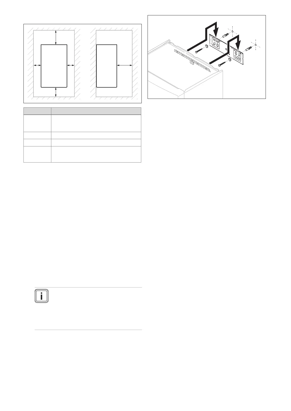
6.4 Minimum clearances
Minimum clearance
A 60/100 mm diameter air/flue pipe: 165 or
248 mm. → See mounting template
80/125 mm diameter air/flue pipe: 276 mm
B 180 mm
C 5 mm
D 500 mm in front of the heat generator to enable
easy access for maintenance work (may be
provided by an opening door)
6.5 Compartment Ventilation
The boilers are very high efficiency appliances.
As a consequence the heat loss from the appliance casing
during operation is very low.
Compartment ventilation is not required if the product is fitted
with a concentric flue system.
6.6 Using the mounting template
▶ Use the mounting template to set the positions of the drill
holes, wall penetrations and to read all of the required
clearances.
6.7 Wall-mounting the product
1. Ensure that the wall or wall-mounting apparatus (e.g.
individual stands) has a sufficient load-bearing capa-
city.
2. Use approved fixing material to secure the unit mount-
ing bracket.
Note
Use suitable fixing material, in accordance
with the structure of the wall on-site, for a
load-bearing capacity of 100 kg.
The supplied fixing material is suitable only
for walls made from concrete and solid
bricks.
3. Wall-mount the product on the unit mounting bracket.
7 Installation
7.1 Prerequisites
7.1.1 Gas supply
In the planning phase, consult the local gas supply company
in order to guarantee the availability of sufficient gas sup-
ply. An existing gas supply line must NOT be used without
consulting the local gas supply company first. The product
must only be connected to a gas supply with a regulated gas
meter. A gas meter must only be installed by the local gas
supply company or a registered Gas Safe Engineer. In Ire-
land, it must only be installed by a registered Gas Installer
(RGII).
An existing gas meter should preferably be checked by the
gas supply company in order to ensure that the gas meter is
suitable for supplying the required gas volume. The compet-
ent person is responsible for designing the gas pipelines in
compliance with BS 6891.
If we assume an acceptable pressure loss of 1 mbar for the
gas pipelines to the unit, we can assume a maximum per-
missible operating pressure of 18 mbar at the product's gas
inlet (Reference BS 6400-1 Clause 6.2 Pressure Absorp-
tion).
Use a gas leak-tightness test to ensure that all connections
for the gas valve assembly to the gas control valve are gas-
tight. Gas pipelines must be installed correctly in compliance
with BS 6891. In Ireland, they must be installed in compli-
ance with IS 813. The entire installation MUST be checked
for gas tightness and be purged in accordance with the spe-
cifications in the listed standards.
7.1.2 Information about the gas group
The product is authorised to be operated with all of the gas
types that are listed in the gas boiler category, see technical
data. In the as-supplied condition, the product must only be
operated with gases of the gas type and/or the gas group for
which they are set, which can be seen on the data plate.
If the product is approved for operation with a different gas
family, you can convert to the new gas family and gas type.
(→ Section 9.18)
 Loading...


