0020308118_05 Installation and maintenance instructions 47
Validity: VU 35CS/1-5 (N-GB) ecoTEC plus 635 OR VUW 30/40CS/1-5 (N-GB)
ecoTEC plus 840
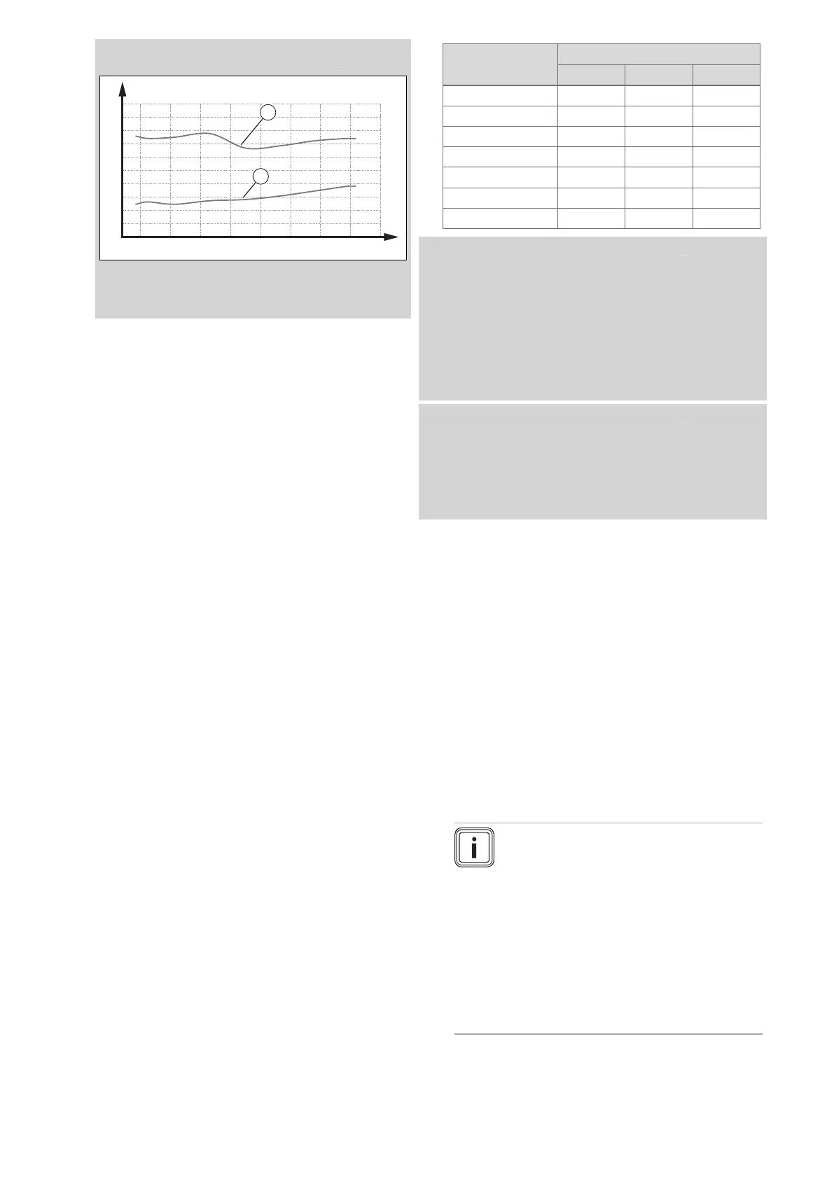
5 1015 2025 30354045
B
4
6
8
10
2
0
A
2
2
1
A O₂ content [vol%]
1 Max. O₂ content,
natural gas
B Heat input [kW]
2 Min. O₂ content,
natural gas
Result:
The value lies outside of the permitted range
▶ Check the total pipe length of the air/flue system;
see the set-up instructions for the air/flue system.
▶ Check the air/flue system for recirculation and
blockages. (→ Section 9.13.2)
▶ Measure the O₂ content at the flue gas analysis
point again and log the measured value in the
benchmark log in the appendix.
▶ If the O₂ content remains outside of the permissible
range, correct the gas-air ratio via D.158 and meas-
ure the O₂ content again at the flue gas analysis
point.
▶ If the O₂ content remains outside of the per-
missible range, replace the control electrode
(→ Section 13.7.14) and reset D.158 to the factory
setting.
▶ Measure the O₂ content at the flue gas analysis
point again and log the measured value.
▶ If the value is still outside of the permissible range,
do not start up the product and, instead, report this
to customer service.
8. Remove the flue gas analyser and close the test open-
ing at the flue gas analysis point.
9.13.5 Checking the gas flow rate
The gas flow rate has been set during production and does
not require adjustment. With the front casing fitted check the
gas flow rate of the boiler as follows:
▶ Check whether the front casing (vacuum chamber) has
been closed tightly.
▶ Start up the product with the check programme P.01.
▶ In addition, ensure that maximum heat can be dissipated
into the heating system by turning up the room thermo-
stat.
▶ Wait at least 5 minutes until the boiler has reached its
operating temperature.
▶ Ensure that all other gas appliances in the property are
turned off.
▶ Measure the gas flow rate at the gas meter.
▶ Compare the measured values with the corresponding
values in the table.
Qnw from the data
plate
H gas in m³/h
Nom. +5% −10%
15.3 1.62 1.70 1.46
18.4 1.95 2.05 1.76
24.7 2.61 2.74 2.35
25.7 2.72 2.86 2.45
28.6 3.03 3.18 2.73
30.6 3.24 3.40 2.92
35.7 3.78 3.97 3.40
Condition: Gas flow rate not in the permissible range
▶ Check the compliance with the local gas group.
(→ Section 9.13.1)
▶ Check the gas supply and monitor the flow pressure dur-
ing the test operation. (→ Section 9.13.3)
▶ Check all of the piping and ensure that the gas flow rates
are correct.
▶ Only put the product into operation once the gas flow
rates have been corrected.
Condition: Gas flow rate in the permissible range
▶ End the check programme P.01.
▶ Allow the boiler to cool down by allowing pump overrun to
operate for a minimum of 2 minutes.
▶ Record the boiler maximum gas flow rate onto the
Benchmark Checklist.
9.14 Thoroughly flushing the heating installation
("hot")
1. Operate the appliance until the boiler and the heating
system are up to temperature.
2. Check the heating system for leaks.
3. Connect a hose to the drain valve located at the lowest
position of the heating system.
4. Shut off the boiler, open the drain valve and all purge
valves on the radiators and allow the water to flow out
of the heating system and the boiler quickly and fully.
5. Close the drain valve.
6. Fill the heating system again with water as described
in Filling the heating installation (→ Section 9.9) and
Purging the heating installation (→ Section 9.10).
7. Re-fill the system until the system design pressure of
0,1 MPa (1,0 bar) is attained.
Note
The actual reading on the digital pressure
gauge should ideally be 0,05 MPa (0,5 bar)
plus an additional pressure corresponding
to the highest point of the system above
the base of the boiler – 10 m head equals
an additional 1 bar reading on the pressure
gauge. The minimum pressure should not
be less than 0,1 MPa (1 bar) in any install-
ation. If the system is to be treated with an
inhibitor it should be applied at this stage in
accordance with the manufacturer’s instruc-
tions.
 Loading...


