64 Installation and maintenance instructions 0020308118_05
10. Insert the new heat exchanger into the grooves on the
back panel.
11. Screw in a new screw tightly on the underside of the
heat exchanger.
12. If you have removed an existing front retainer, use two
screws each to screw the retainer in tightly.
13. Secure the condensate discharge hose on the heat
exchanger.
14. Insert the flow/return pipes into the heat exchanger as
far as they will go. When doing so, replace all of the
seals.
15. Secure the clips to the flow/return pipe.
16. Install the compact thermal module. (→ Section 12.7.2)
17. Install the side casing. (→ Section 13.7.16)
18. Install the connector for the air/flue pipe.
(→ Section 7.2.6.2)
19. Fill the heating installation. (→ Section 9.9)
20. Purge the heating installation. (→ Section 9.10)
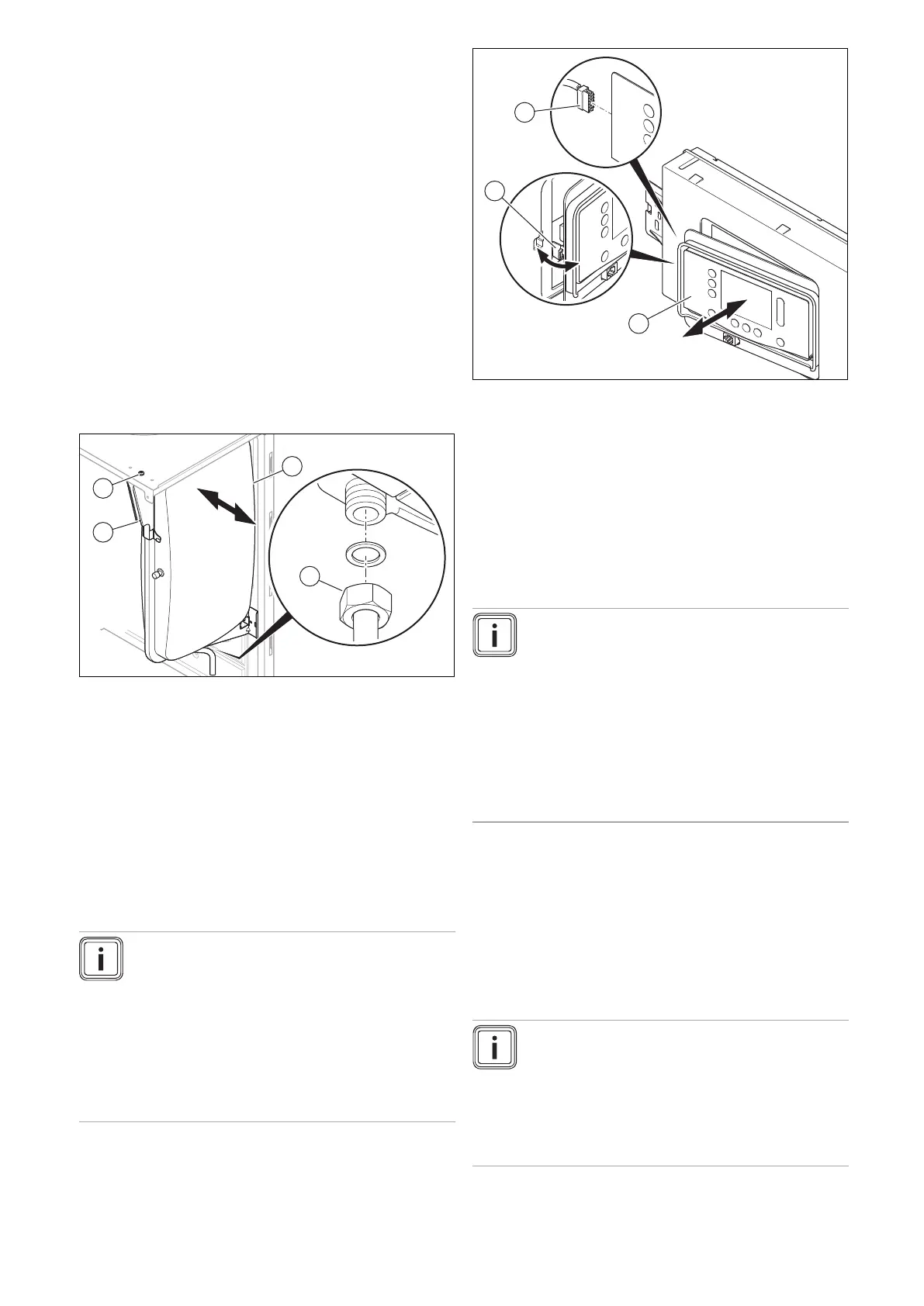
13.7.9 Replacing the expansion vessel
1. Undo the nut (3).
2. Undo the screw (1) on the support plate (4) and re-
move the support plate.
3. Pull out the expansion vessel (2) to the side.
4. Insert the new expansion vessel into the product.
5. Screw in the nuts below the expansion vessel tightly.
Use a new seal for this.
6. Use the screw to secure the support plate.
7. Fill the heating installation. (→ Section 9.9)
8. Purge the heating installation. (→ Section 9.10)
13.7.10 Replace the display
Note
Spare parts must only be used once.
If you only replace the display, when the product
is switched on, the new display adopts the para-
meters that were previously set from the PCB that
was not replaced. After replacing the display as-
sembly, the DSN code (Device Specific Number)
is transferred to the respective replaced assembly
and is written to its memory, where it cannot be
deleted.
1. Release the display (1) from the retainer (2) on the left-
hand side.
2. Remove the plug (3) from the display.
3. Replace the display.
4. Plug the plug into the new display.
5. Install the display in the retainer.
6. Establish the power supply.
◁ The DSN code is transferred from the PCB to the
display.
13.7.11 Replacing the PCB
Note
Spare parts must only be used once.
If fault F.064 is present, check diagnostics code
D.166 before you replace the PCB.
If you only replace the PCB, when the product is
switched on, the new PCB adopts the parameters
that were previously set from the display that was
not replaced. After replacing the PCB assembly,
the DSN code (Device Specific Number) is trans-
ferred to the respective replaced assembly and is
written to its memory, where it cannot be deleted.
1. Open the electronics box. (→ Section 7.10.3)
2. Replace the PCB in accordance with the set-up and
installation instructions supplied.
3. Close the electronics box. (→ Section 7.10.4)
4. Establish the power supply.
◁ The DSN code is transferred from the display to
the PCB.
13.7.12 Replacing the PCB and the display
Note
Spare parts must only be used once.
After replacing the display and PCB assemblies,
all of the installation-specific settings are deleted.
If required, use the installation-specific settings
from the "Diagnostics codes" table in the appendix
if they have been noted there. (→ Appendix D)
 Loading...


