0020308118_05 Installation and maintenance instructions 33
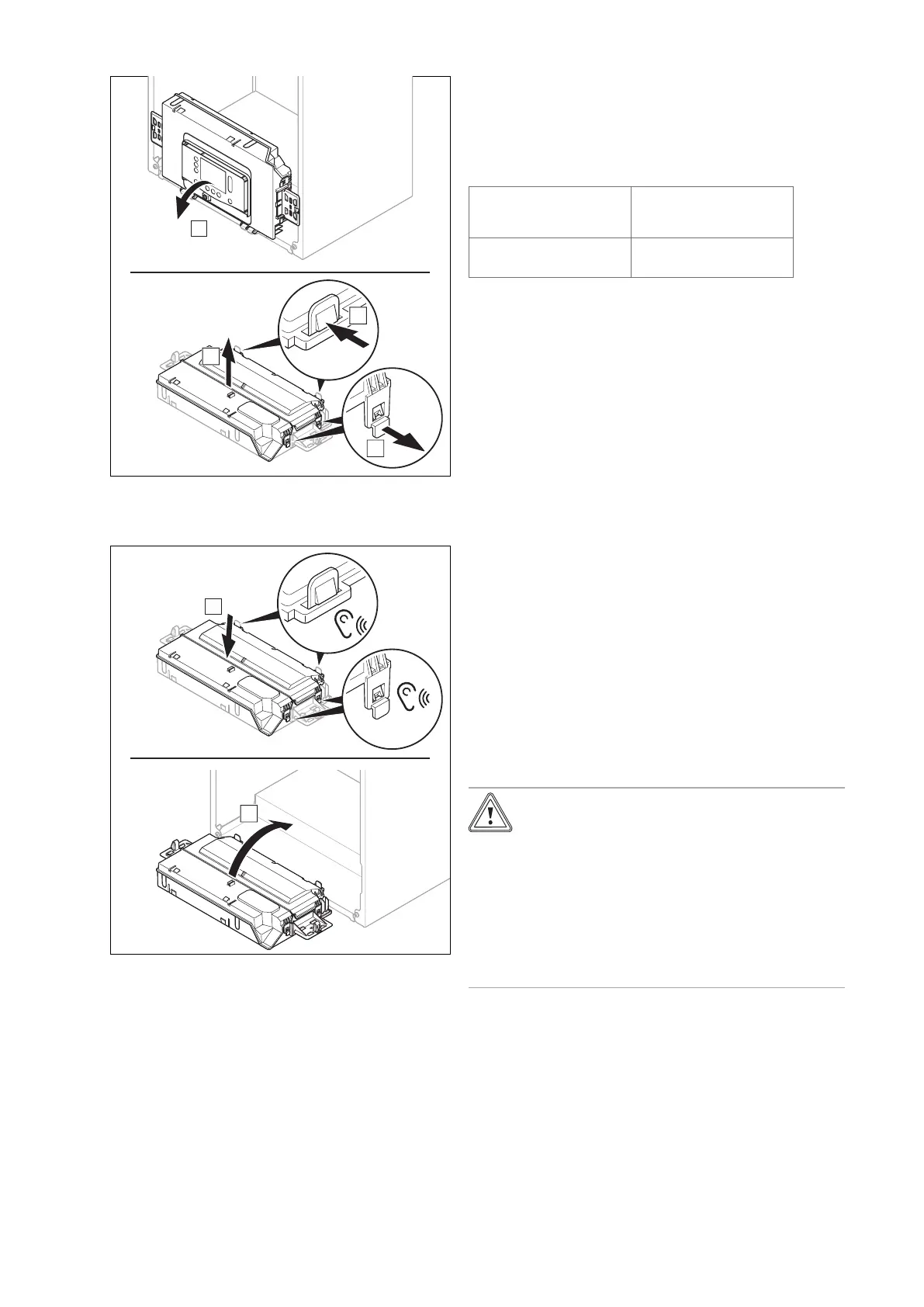
7.10.3 Opening the electronics box
1.
2. Ensure that you do not load the electronics box.
7.10.4 Closing the electronics box
1.
2. Ensure that the retainers on the right- and left-hand
side of the electronics box have been installed cor-
rectly.
7.10.5 General information
7.10.5.1 Requirements for the mains voltage and
sensor lines
Observe the following requirements for the mains voltage
and sensor lines:
Line cross-section
Supply line for mains
voltage (pump or mixer
mains cable)
≥ 1.5 mm²
(≥ 0.0023 in²)
Sensor line (extra low
voltage)
≥ 0.75 mm²
(≥ 0.00116 in²)
Line length
– Sensor lines: ≤ 50 m (≤ 164 ft ‒ 1 in)
7.10.5.2 Requirements for the eBUS line
Observe the following rules when routing the eBUS lines:
▶ Use twin-core cables.
▶ Never use shielded or twisted cables.
▶ Use only appropriate cables, e.g. NYM or H05VV (-F/-U).
▶ Observe the permissible total length of 125 m. For a
total length of up to 50 m, a conductor cross-section of
≥0.75 mm² applies; from 50 m upwards, a conductor
cross-section of 1.5 mm² applies.
In order to prevent faults in the eBUS signals (e.g. due to
interferences):
▶ Maintain a minimum clearance of 120 mm to power sup-
ply cables or other electromagnetic sources of interfer-
ence.
▶ For parallel routing to mains connection lines, guide the
cables in accordance with the applicable regulations, e.g.
on cable trays.
▶ Exceptions: For wall breaks and in the electronics box, it
is acceptable to not reach the minimum clearance.
7.10.5.3 Feeding through and correctly routing the
cable
Caution.
Risk of material damage caused by incor-
rect installation.
Mains voltage at incorrect terminals and plug
terminals may destroy the electronics.
▶ Do not connect any mains voltage to the
eBUS terminals (+/-).
▶ Only connect the connection cable to the
terminals marked for the purpose.
1. For eBUS lines the wire type can be multi strand cable
or solid core. There is no requirement for Cat 5 cable to
be used.
 Loading...


