54 Installation and maintenance instructions 0020308118_05
▶ Inform the end user that they must not store or use explo-
sive or highly flammable substances (such as petrol, pa-
per or paint) in the installation room of the product.
▶ Complete and sign off the Benchmark commissioning
check list.
▶ Complete and sign off the guarantee documentation.
12 Inspection and maintenance
12.1 Complete Service Interval Record section
▶
After servicing, complete the relevant Service Interval
Record section of the Benchmark Checklist located on
the inside back pages of this document.
12.2 Using original seals
If you replace components, use only the enclosed new ori-
ginal seals; additional sealing materials are not required.
12.3 Maintenance interval
A service interval can be defined in two ways. A service in-
terval must not be greater than 1 year.
Use D.084 to establish the link to the countdown of operating
hours.
Use D.161 to establish the link to a date.
The service message regarding the event that occurs earlier
appears (the hours have elapsed or the date is reached).
If you only set one of the two diagnostics codes (D.084 or
D.161), the other diagnostics code in each case is automat-
ically reset to the factory setting.
If you select Not set for D.084, the service message regard-
ing the operating hours is deactivated. The service message
for the date remains active and cannot be deactivated.
The service message regarding the event that occurs earlier
appears (the hours have elapsed or the date is reached).
Once the service work is complete, you must set the main-
tenance intervals again. (→ Section 12.3.1)
12.3.1 Setting/resetting the maintenance interval
1. Set diagnostics code D.084 or D.161. (→ Section 8.3)
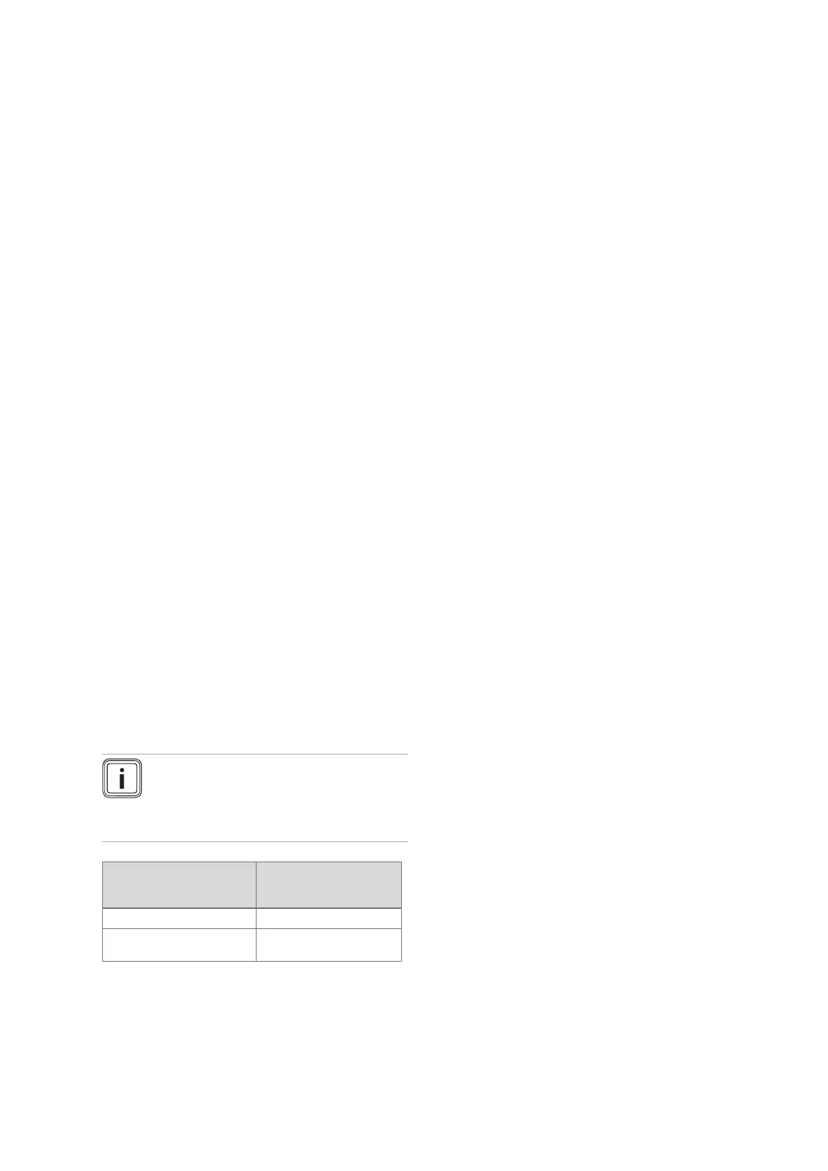
Note
The operating hours until the next inspec-
tion/maintenance must be set individually
(depending on the type of unit and the heat
output).
Operating mode Guideline value for the
operating hours (in
relation to one year)
Heating mode 4000 h
Heating and domestic hot
water mode
5000 h
2. Exit the diagnostics codes. (→ Section 8.3.1)
3. Exit the menu level. (→ Section 8.8)
12.4 Actuator test
MENU → SETTINGS → Installer level → Test modes → Ac-
tuator test
The actuator test allows you to actuate and test individual
components in the heating installation.
Actuator test (→ Appendix H)
12.5 Inspection and maintenance
▶ You must carry out an annual inspection of the product.
The annual inspection can be effectively performed
without removing components by requesting data from
the Diagnostics codes, carrying out the simple visual
checks indicated in the table in the appendix and per-
forming a flue gas measurement. The maintenance
intervals and their scope are determined by the heating
engineer based on the condition of the boiler found
during the inspection. All inspection and maintenance
work should be performed in the order specified in the
table in the appendix.
During any inspection and maintenance or after change
of parts of the combustion circuit, the following must be
checked:
– The boiler has been installed in accordance with the rel-
evant installation instructions.
– The integrity of the flue gas installation and flue seals is
in accordance with the relevant flue installation instruc-
tions enclosed.
– Visual, the integrity of the boiler combustion circuit and
relevant seals (paying particular attention to the burner
door seal).
– The gas inlet working pressure at maximum rate.
– The gas flow rates.
– Correctness of electrical, water and gas connections.
– Correctness of the water pressure.
– The condition of the whole system, in particular the con-
dition of radiator valves, evidence of leakage from the
heating system and dripping taps.
▶ Correct any faults before proceeding.
12.6 Preparing the maintenance work
1. Switch off the product.
2. Disconnect the product from the power grid.
3. Remove the front casing. (→ Section 7.10.2)
4. Close the gas stopcock.
5. Close the service valves in the heating flow and in the
heating return.
6. Close the service valve in the cold water pipe.
7. Drain the product to clean hydraulic components
(→ Section 12.9).
8. Ensure that water does not drip on live components
(e.g. the electronics box).
9. Use only new seals and o'ring. Do not use additional
compounds.
 Loading...


