0020308118_05 Installation and maintenance instructions 37
7.10.8.1.2 Traditional room controls
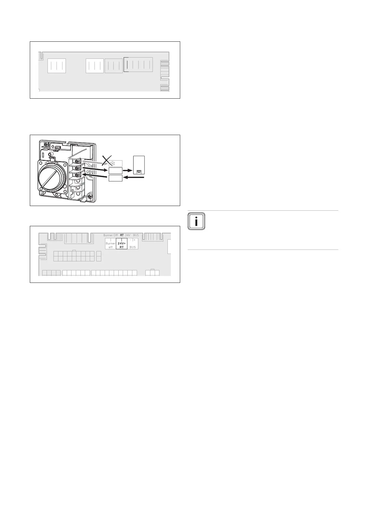
Option 1: 230 V room thermostat
aX12b
X1
CH Pump
RT 230V Mains
X19
Opt 1
X16
Fan
X11
A 230 V room thermostat can be connected to this single-
pole interface. Only the phase switched by the thermostats
is connected. The room thermostat must be given a separate
external 230 V power supply.
Option 2: 24 V room thermostat
A 24 V room thermostat is connected to this interface and
used to transmit the switching signal.
7.10.8.1.3 Smart room controls
Smart room controls are available when an eBUS room con-
trol and a suitable Vaillant gateway are present. The room
control can be set and operated using the Vaillant app. For
connection, follow the instructions in the enclosed installation
instructions.
7.10.8.2 Weather-compensated control
A room control responds only indirectly to the weather condi-
tions. On the other hand, a weather-compensated control re-
sponds directly to the weather conditions. Using an outdoor
temperature sensor, the heat generator is operated depend-
ing on the outdoor temperature according to requirements.
Weather-compensated controls are eBUS controls. The out-
door temperature sensor is also connected to the PCB using
a connection plug. For connection, follow the instructions in
the enclosed installation instructions.
A weather-compensated eBUS control can also be intelli-
gently set and operated in conjunction with a Vaillant gate-
way and the relevant Vaillant app.
7.10.8.3 Control modules
The heat generator can be combined with various control
modules. Control modules are necessary if the installation
comprises an external 3-port valve, buffer cylinder, etc. For
installation and operation, follow the instructions in the en-
closed installation and operating instructions.
7.10.8.4 myVAILLANT Connect (VR 940f)
communication unit (Gateway)
A gateway enables remote communication between the user
and heat generator. The gateway can be connected to this
product via a special external interface.
Power supply and eBUS communication take place directly
via this interface. After installation, there is the option to set
and operate the control using the Vaillant app. Certain mod-
els can also be combined with other smart home solutions.
For installation, see the communication unit's installation
instructions.
7.10.8.5 sensoROOM pure (VRT 50/2)
The sensoROOM pure (VRT 50/2) is an eBUS room control.
If this control is combined with this heat generator, it is pos-
sible to configure time periods using the control display; to
do so, see the heat generator's operating instructions.
Note
If a sensoROOM pure (VRT 50/2) is connected,
the flow temperature must be set on the room
temperature control and, if required, the heating
mode must also be switched off there.
 Loading...


