66 Installation and maintenance instructions 0020308118_05
burner insulating mat on the rear of the combustion
chamber cover.
5. Remove the sealing residue from the burner flange.
Caution.
Risk of material damage caused by touch-
ing and cleaning.
The electrode may emit incorrect signals due
to changes in the surface.
▶ Only touch an electrode at the ceramic
section.
▶ Never clean an electrode.
6. Insert the new ignition electrode with a new seal (2).
7. Use two new screws to screw the ignition electrode in
tightly. Tightening torque, see appendix.
8. Reconnect the plug for the ignition electrode's ignition
line.
9. Reconnect the plug on the earth cable.
13.7.14 Replacing the control electrode
Danger!
Risk of death from hot flue gases!
Seals, screws and insulation on the control
electrode and combustion chamber must not
be damaged.
▶ Avoid damaging the burner insulating
mat on the back panel of the combustion
chamber cover.
▶ Replace the burner insulating mat as soon
as it shows signs of damage.
▶ Replace the seal and screws each time
you replace the control electrode.
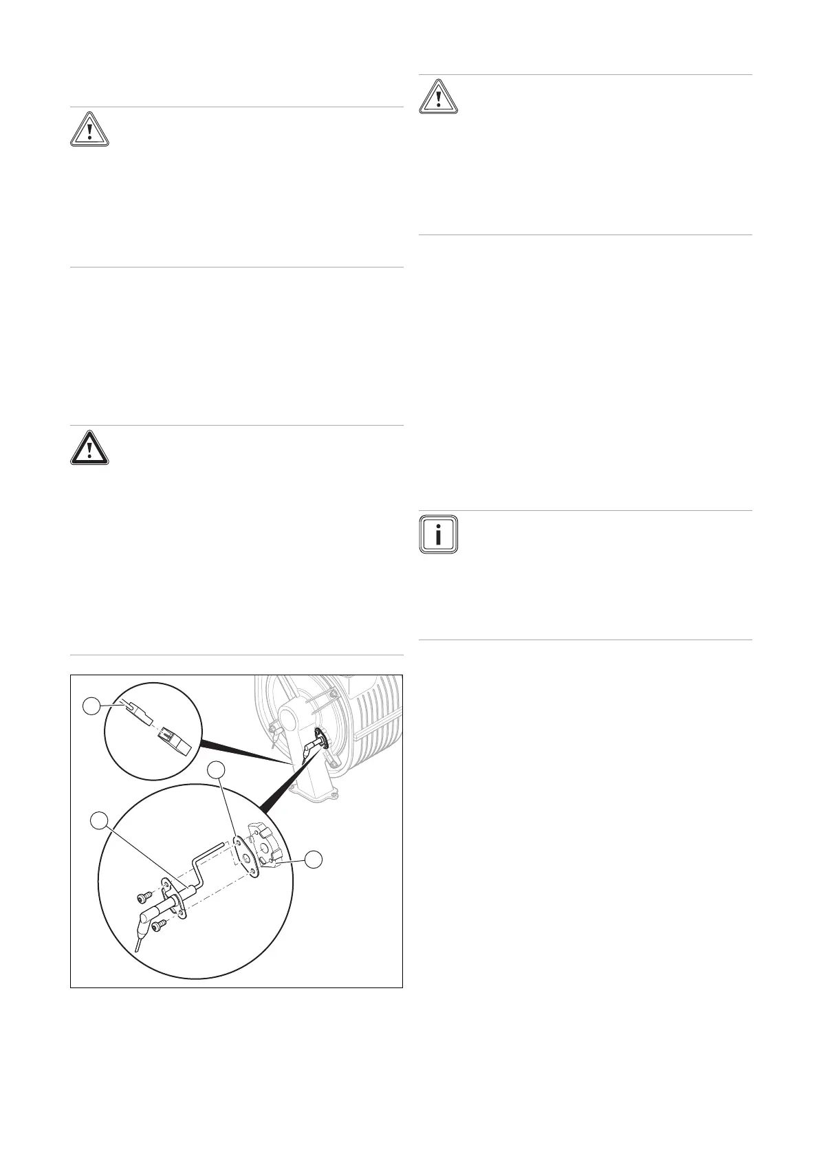
1. Remove the plug (1) for the control electrode's cable.
2. Unscrew both screws.
3. Thread the control electrode (4) carefully out of the
burner flange (3). Ensure that you do not damage the
burner insulating mat on the rear of the combustion
chamber cover.
4. Remove the sealing residue from the burner flange.
Caution.
Risk of material damage caused by touch-
ing and cleaning.
The electrode may emit incorrect signals due
to changes in the surface.
▶ Only touch an electrode at the ceramic
section.
▶ Never clean an electrode.
5. Insert the new control electrode with a new seal (2).
6. Use two new screws to screw the control electrode in
tightly. Tightening torque, see appendix.
7. Reconnect the plug for the control electrode's ignition
line.
8. Install the front casing. (→ Section 7.11)
9. Open the gas stopcock.
10. Connect the product to the power supply.
11. Activate diagnostics code D.147 via D.146.
(→ Section 8.3)
12. Set diagnostics code D.147 to New electrode
(→ Section 8.3).
13. Check the O₂ content. (→ Section 9.13.4)
13.7.15 Routing wiring harnesses
Note
High temperatures may damage wiring
harnesses.
Incorrect routing of the wiring harnesses may lead
to electromagnetic faults.
To prevent damage and faults, install the wiring
harnesses as shown in the figure.
 Loading...


