34 Installation and maintenance instructions 0020308118_05
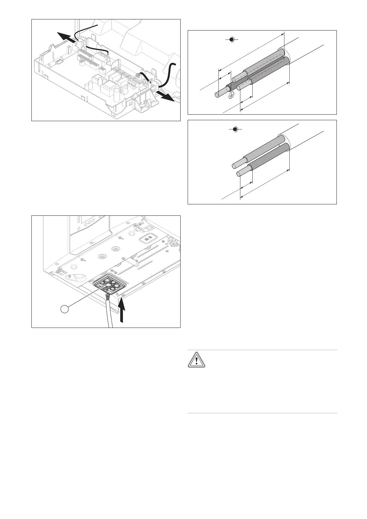
2. Correctly route the connection cables for the compon-
ents that are to be connected in the electronics box:
24 V/ eBUS -> left-hand area, 230 V -> right-hand
area.
3. Run power cables separately from signal cables. Inter-
ference from power cables may induce spurious faults
on signal cables. Ensure that there is at least 100 mm
separation from each other.
4. Ensure the cables are of sufficient length to allow the
electronics box to be opened to the service position.
5. Use the strain reliefs in the electronics box.
6. If required, shorten the connection cables correctly.
7. Route the connection cables of the components to be
connected through the grommets (1) provided on the
underside of the product on the left.
8. Ensure that the grommet is plugged in correctly and
that the cables have been routed correctly.
9. Take care when piercing the grommets that an air gap
isn't created once the wire has been fitted.
7.10.5.4 Stripping the cables correctly
6 – 8 mm
6
– 8 mm
L
N
230 V
≥ 30 mm
≥ 40 mm
1. Strip the flexible cables as shown in the figure. In doing
so, ensure that the insulation on the individual conduct-
ors is not damaged.
2. Only strip inner conductors just enough to establish
stable connections.
3. When stripping the wires, ensure copper strands do not
fall into the control box.
4. To avoid short circuits resulting from loose individual
wires, fit conductor end sleeves on the stripped ends of
the conductors.
5. Screw the respective plug to the connection cable.
6. Check whether all conductors are inserted mechanic-
ally securely in the plug terminals. Remedy this if ne-
cessary.
7. Plug the plug into the associated PCB slot.
(→ Appendix L)
7.10.6 Connecting the product with a fixed
connection
Caution.
Risk of material damage due to high con-
nected voltage.
At mains voltages greater than 253 V, elec-
tronic components may be damaged.
▶ Make sure that the rated voltage of the
mains is 230 V.
1. Observe all valid regulations.
2. Ensure that the mains voltage is 230 V.
3. Provide one common power supply for the boiler and
for the corresponding control:
 Loading...


