0020308118_05 Installation and maintenance instructions 31
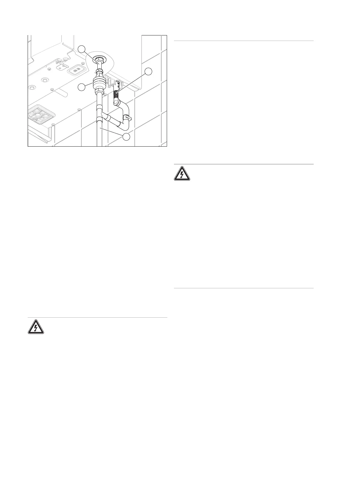
7.9 Installing combined condensate and
pressure relief valve
1. Install the drain pipe for the expansion relief valve (4)
in such a way that it does not interfere with the removal
and fitting of the lower section of the siphon.
2. Install common drain pipework (2) for the expansion
relief valve's drain pipe and the condensate adapter (1)
(→ Section 7.8).
3. This must be carried out in such a way that the pres-
sure relief valve pipework does not come into con-
tact with condensate. This can be achieved by con-
necting the pressure relief valve outlet above the out-
let for condensate. See diagram. In accordance with
BS6798:2014, the discharge from the pressure relief
valve must be visible. This could be achieved directly
by use of a tundish (3) or clear piping (if connecting to
a soil stack it will require a second trap or sealed tun-
dish or similar).
4. Ensure that discharged water or steam cannot cause
injury to persons or damage to electronic components.
5. Ensure the discharge pipe work is installed, routed and
terminated correctly to minimise the risk of freezing up.
7.10 Electrical installation
Only qualified electricians may carry out the electrical install-
ation.
Danger!
Risk of death from electric shock!
The power supply terminals L and N remain
live:
▶ Disconnect the product from the power
supply by switching off all power supplies
at all poles (electrical partition with a con-
tact gap of at least 3 mm, e.g. fuse or cir-
cuit breaker). Information on safe isolation
can be found in the Health and Safety Ex-
ecutive guidance HSG85.
▶ Secure against being switched back on
again.
▶ Wait for at least 3 minutes until the capa-
citors have discharged.
▶ Check that there is no voltage. Use test
equipment approved to GS38 to confirm
that the electricity supply is disconnected.
All work must comply with the current IET Wiring Regula-
tions.
The isolator shall be situated next to the appliance for new
systems and, where practicable, replacement appliances.
The mains electrical supply to the appliance must be through
a fused double pole isolator.
Any additional components that are connected to the appli-
ance that require 230 Volts must be connected to the same
supply as the appliance.
External fuse 3 Amps.
When stripping the wires, ensure copper strands do not fall
into the electronics box.
The product must be earthed.
7.10.1 Installing the product in a wet room
Danger!
Risk of death from electric shock!
If you install the product in a room with high
levels of moisture, e.g. a bathroom, observe
the nationally recognised technical standards
for electrical installations.
▶ Never use a connection cable with
earthed plug when installing the product in
a moist environment.
▶ Connect the product using a fixed con-
nection and an electrical partition with a
contact gap of at least 3 mm (e.g. fuses or
power switches).
▶ Any switch or appliance control using
mains electricity must not be within reach
of a person using the bath or shower.
 Loading...


