40 Installation and maintenance instructions 0020308118_05
Num-
ber
Check Yes
(✓)
5 Isolation is via a double pole switched
fused spur or 3 pin fused plug in
unswitched shuttered socket
Flue system
6 The flue type and length conforms with
the boiler model type and maximum
lengths allowable (including bend
restrictions)
7 All flue joints correctly connected and flue
lengths correctly supported
Condensate
8 Condensate termination point checked
and correctly insulated if external
9 Condensate trap filled and re-sealed in
correct position
Gas
10 Gas Tightness test completed
11 Standing gas pressure checked – and
turned on if safe
Water
12 Water Heating circuits are prepared for
first cold fill
13 Mains water treatment installed (Combi
boilers)
14 Heating system has been cleansed thor-
oughly and suitably treated
15 Heating system filter installed and valves
open
▶ Follow the installation wizard instructions that appear on
the interface, follow each instruction in turn until com-
plete.
Tips/hints for the new ecoTEC/1-5
Electronic heat engine
– You don't need any tools, just use the relevant diagnostic
points, e.g. D.000, D.085, D.146 - D.147, D.156 - D.157,
D.164.
Intelligent hydraulics
– Yes, there is a bypass, but it has a different task. Use the
properties of the pump with D.170 and D.171 bis D.175.
User interface
– Use the new possibilities of the interface, e.g. for the ex-
haust gas analysis use the new chimney sweep function.
9.2 Carrying out the initial start-up
Initial start-up must be carried out by a customer service
technician or an authorised competent person using the
Benchmark Checklist. The Benchmark Checklist in the ap-
pendix (→ Appendix M) of the installation instructions must
be filled in and stored carefully along with the unit's docu-
mentation.
▶ Carry out the start-up procedure using the Benchmark
Checklist in the appendix.
▶ Fill out and sign the Benchmark Checklist.
9.3 Checking and treating the heating
water/filling and supplementary water
Caution.
Risk of material damage due to poor-qual-
ity heating water
▶ Ensure that the heating water is of suffi-
cient quality.
▶ Before filling or topping up the installation, check the
quality of the heating water.
Checking the quality of the heating water
▶ Remove a little water from the heating circuit.
▶ Check the appearance of the heating water.
▶ If you ascertain that it contains sedimentary materials,
you must desludge the installation.
▶ Use a magnetic rod to check whether it contains mag-
netite (iron oxide).
▶ If you ascertain that it contains magnetite, clean the in-
stallation and apply suitable corrosion-inhibition meas-
ures (e.g. fit a magnetite separator).
▶ Check the pH value of the removed water at 25 °C.
▶ If the value is below 8.2 or above 10.0, clean the installa-
tion and treat the heating water.
▶ Ensure that oxygen cannot get into the heating water.
Checking the filling and supplementary water
▶ Before filling the installation, measure the hardness of the
filling and supplementary water.
Treating the filling and supplementary water
▶ Observe all applicable national regulations and technical
rules when treating the filling and supplementary water.
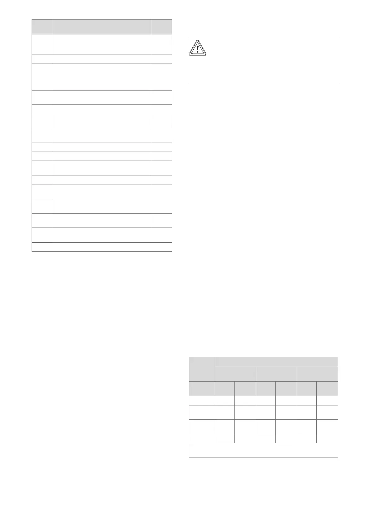
Provided the national regulations and technical rules do not
stipulate more stringent requirements, the following applies:
You must treat the filling and supplementary water in the
following cases
– If the entire filling and supplementary water quantity dur-
ing the operating life of the system exceeds three times
the nominal volume of the heating installation, or
– If the guideline values listed in the following table are not
met, or
– If the pH value of the heating water is less than 8.2 or
more than 10.0.
Total
heating
output
Water hardness at specific system volume
1)
≤ 20 l/kW
> 20 l/kW
≤ 40 l/kW
> 40 /kW
kW
ppm
CaCO₃
mol/
m³
ppm
CaCO₃
mol/
m³
ppm
CaCO₃
mol/
m³
< 50 < 300 < 3 150 ≤ 1.5 5 0.05
> 50
to ≤ 200
200 < 2 150 ≤ 1.5 5 0.05
> 200
to ≤ 600
150 < 1.5 5 0.05 5 0.05
> 600 5 0.05 5 0.05 5 0.05
1) Nominal capacity in litres/heat output; in the case of multi-
boiler systems, the smallest single heat output is to be used.
 Loading...


