36 Installation and maintenance instructions 0020308118_05
Low voltage connection area (SELV)
X12b
X1
CH Pump
RT 230V Mains
X19
X41X36
X100
Opt 1
X16
Fan
X11
X24
X20
X31
X32
X41X36
X100
X24
X20
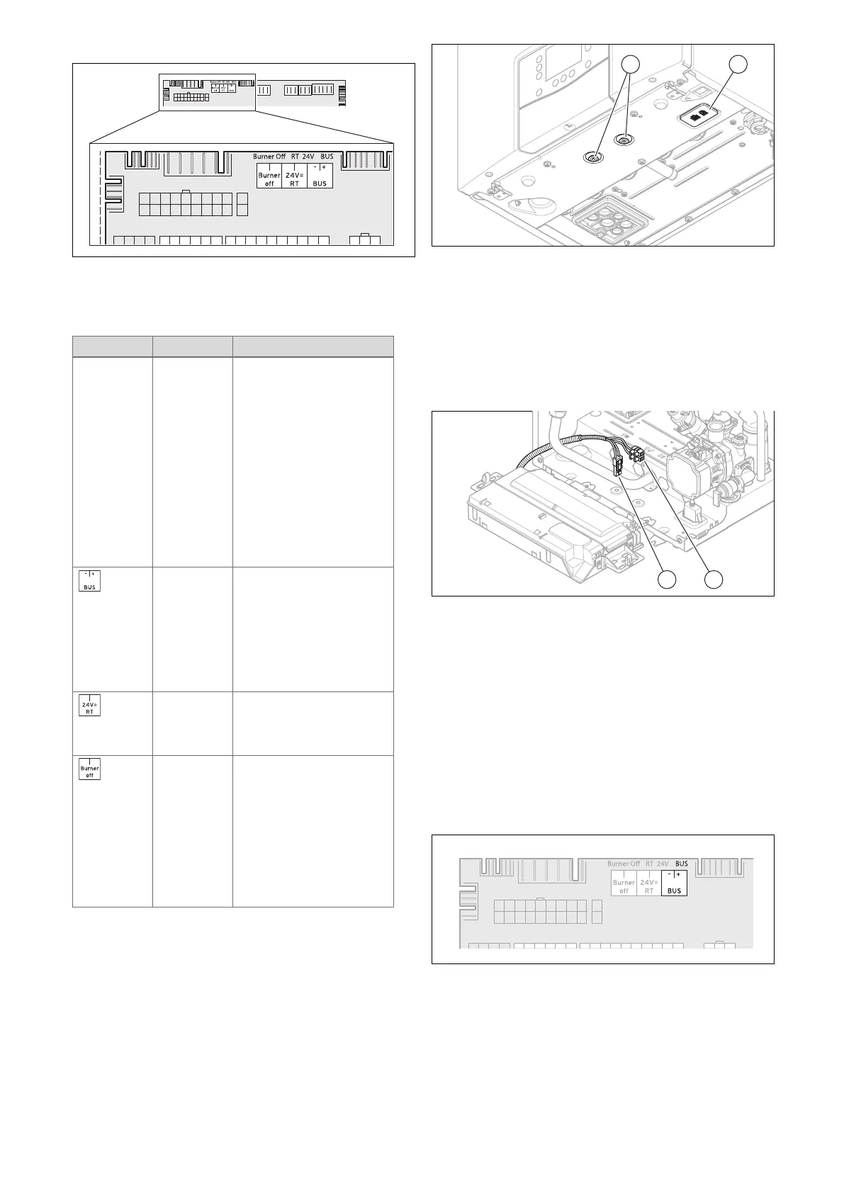
– General eBUS interface for controls
– 24 V thermostat
– Limit thermostat
Slot Item Function
X100 Caution.
Risk of material damage
caused by incorrect installa-
tion.
Mains voltage at incorrect
terminals and plug terminals
may destroy the electronics.
► Do not connect the mains
voltage to the eBUS termin-
als (+/-) or to the other ter-
minals at X100.
► Connect mains voltage
only to the terminals that are
marked for this.
X100 Bus connection control
Vaillant control with eBUS
communication can be con-
nected to this slot.
Note
When using the eBUS, the
bridge at the 24 V RT plug
must be inserted.
´X100 24 V DC room thermostat
Prerequisite: You are not us-
ing an eBUS control and the
existing bridge is removed.
X100 Burner off / limit thermostat
Separate protective thermo-
stat contact, independently
of the eBUS and 24 V RT.
Use when protecting against
overheating for underfloor
heating and/or low-temperat-
ure systems.
Prerequisite: Remove the
bridge.
Additional connection options
Communication unit (gateway module)
– Interface (Customer Interface Module)
The interface (1) and the bracket (2) are located below the
product. A control module can be installed and connected
here. The slot includes the power supply and the eBUS com-
munication for the gateway.
Signal connection for cylinder charging
– Cylinder thermostat (switching contact: On/off) (VU only)
– Cylinder temperature sensor (measurement of the cylin-
der temperature) (VU only)
The screw connection for the switching contact (thermostat)
(2) is not located on the PCB, but rather on the wiring har-
ness on the bottom left in the product.
The plug-in connection for connecting a Vaillant cylinder
temperature sensor (1) is not located on the PCB, but rather
on the wiring harness on the bottom left in the product.
7.10.8 Control systems
7.10.8.1 Room control (connection)
The product can be combined with various room controls.
7.10.8.1.1 eBUS room controls
Room controls which use eBUS are connected to this
interface. The interface supplies the control with electricity
and is also used for signal communication.
 Loading...


