2.5 Determining shims
⇒ “2.5.1 Notes on gearbox adjustment”, page 149
⇒ “2.5.2 Calculating shims for clutch housing”, page 150
⇒ “2.5.3 Calculating shims for gearbox housing”, page 161
2.5.1 Notes on gearbox adjustment
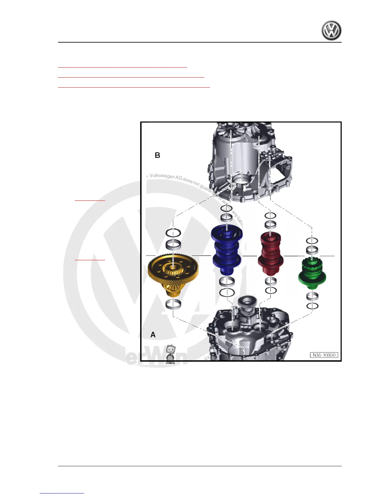
Adjustment work is divided into 2 »sections«:
A - This involves finding shims
that are inserted into clutch
housing.
❑ This is the start of the
work. Objective is to
align output shafts 1 to 3
in clutch housing »in
one imaginary plane«.
This »imaginary plane«
is defined by face end of
outer input shaft. How
this is done:
⇒ page 150 .
B - During assembly of gear‐
box, »thickness« of these
shims determines force with
which shafts are »clamped«
between both halves. These
shims are inserted in gearbox
housing.
❑ How this is done:
⇒ page 161
• Only once correct shims
-A- have been calculated
for clutch housing, or if
there is no need for meas‐
urement, can shims -B- be
determined.
• Therefore, do not calculate
shims -B- until shims -A-
are OK.
• Work with intact tools, make sure the workplace is clean.
• Avoid temperature differences between gearbox and adjusting
tool.
• Flange surfaces of both housing halves should be smooth and
neither »indented nor damaged«.
• Only fit measuring table when there are guide bushes in hous‐
ing.
• Do not swap over bearing races of same size, always renew
bearings on a shaft jointly.
Golf 2013 ➤
7-speed dual clutch gearbox 0CW - Edition 10.2012
2. Output shaft 149

 Loading...