12.2.6 Removing and installing steering col‐
umn switch base
Note
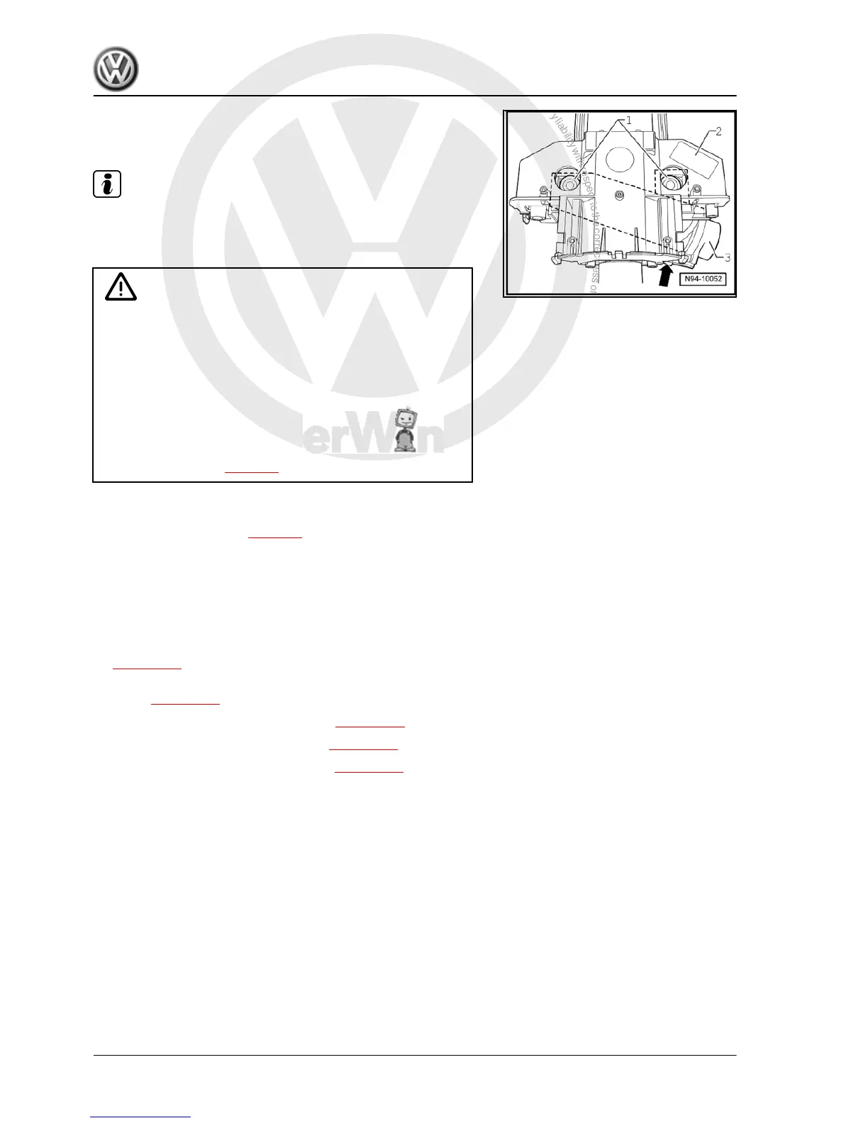
To remove the steering column switch base -2-, the shear bolts
of the steering lock housing must be drilled out. To reinstall, new
shear-head bolts -1- are required ⇒ Parts catalogue (ETKA) .
Caution
♦ Ensure that the components mounted on the carrier have
been removed before drilling out the shear-head bolts.
♦ The drilling operation can cause swarf to penetrate the
adjacent components resulting in damage and/or mal‐
function!
♦ Keep to the specified sequence when removing compo‐
nents.
♦ When battery -A- is disconnected and reconnected, the
procedure described in the workshop manual must be
strictly observed ⇒ page 4 .
Removing
– Disconnect battery -A- ⇒ page 4 .
Remove the following components in sequence:
– Remove steering wheel ⇒ General body repairs, interior; Rep.
gr. 69 .
– Remove steering column trim ⇒ General body repairs, interior;
Rep. gr. 68 .
– Remove steering column electronics control unit -J527-
⇒ page 321 .
– Remove airbag coil connector and return ring with slip ring -
F138- ⇒ page 322 .
– Remove steering angle sender -G85- ⇒ page 323 .
– Remove turn signal light switch -E2- ⇒ page 324 .
– Remove windscreen wiper switch -E- ⇒ page 324 .
Golf Variant 2007 ➤ , Golf Variant 2010 ➤ , Jetta 2005 ➤
Electrical system - Edition 07.2010
326 Rep. gr.94 - Lights, bulbs, switches - exterior

 Loading...