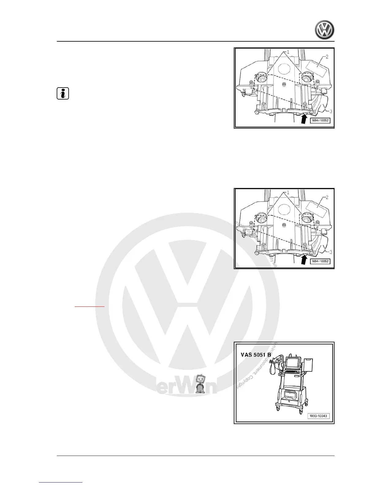
– Separate connector -arrow- on reader coil -3-.
The base can be removed once all the components mounted to
it have been removed:
– Drill out bolts -1- of steering lock housing -3-.
Note
Bolts M8 -1-, core diameter 6.8 mm
– Pull steering lock housing and steering column switch base
-2- backwards off steering column.
– Take steering lock housing off steering column switch base.
Installing
Carry out installation in the reverse sequence, noting the follow‐
ing:
– Place the steering lock housing into the steering column switch
base.
– Push steering column switch base -2- as far as possible onto
steering column.
– Fit connector -arrow- on reader coil -3-.
– Secure steering lock housing using new shear bolts -1- to
steering column.
– Tighten shear bolts -1- until bolt heads shear off.
12.3 Steering column electronics control unit
-J527-
Removing and installing steering column electronics control unit
-J527- ⇒ page 321 .
12.3.1 Coding steering column electronics con‐
trol unit -J527-
Special tools and workshop equipment required
♦ Vehicle diagnosis, testing and information system -VAS
5051B-
Golf Variant 2007 ➤ , Golf Variant 2010 ➤ , Jetta 2005 ➤
Electrical system - Edition 07.2010
12. Steering column switch 327

 Loading...