– Remove noise insulation ⇒ General body repairs, exterior;
Rep. gr. 50 .
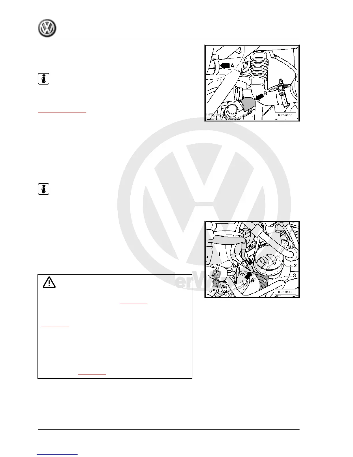
• Installation view shows vehicle from underneath:
Note
Note installation position of cable routing and heat insulation!
Installation position exhaust gas recirculation valve 2 -N213-
⇒ Item 4 (page 495)
– Clip on heat insulation -arrow B- and push heat insulation off
connector.
– Pull off connector from exhaust gas recirculation valve 2 -
N213- .
– Separate cable tie -arrow A-.
• Installation view of engine compartment:
– Remove intake hose ⇒ 4-cyl. diesel engine (2.0 l engine,
common rail); Rep. gr. 23 .
Note
Note installation position of cable routing before you slide out ca‐
ble!
– Slide cable -1- out carefully between induction hood of turbo‐
charger -2- and preheating hose -3- -arrow A-.
– Carefully remove entire wiring harness for engine from engine
compartment.
Installing
Carry out installation in the reverse sequence, noting the follow‐
ing:
Caution
It is essential to comply with working sequence »Removing and
installing glow plug connectors« ⇒ page 492 !
Ensure all connectors are fitted securely.
Attach heat insulation mats in original installation position
⇒ page 491 .
Always renew self-locking nuts, seals and securing clips.
Hose connections are secured with spring-type clips.
It is recommended that spring-type clips should be installed
using spring-type clip pliers -VAS 6362- or hose clamp pliers -
VAS 6340- .
Observe notes ⇒ page 490 .
Golf Variant 2007 ➤ , Golf Variant 2010 ➤ , Jetta 2005 ➤
Electrical system - Edition 07.2010
506 Rep. gr.97 - Wiring

 Loading...