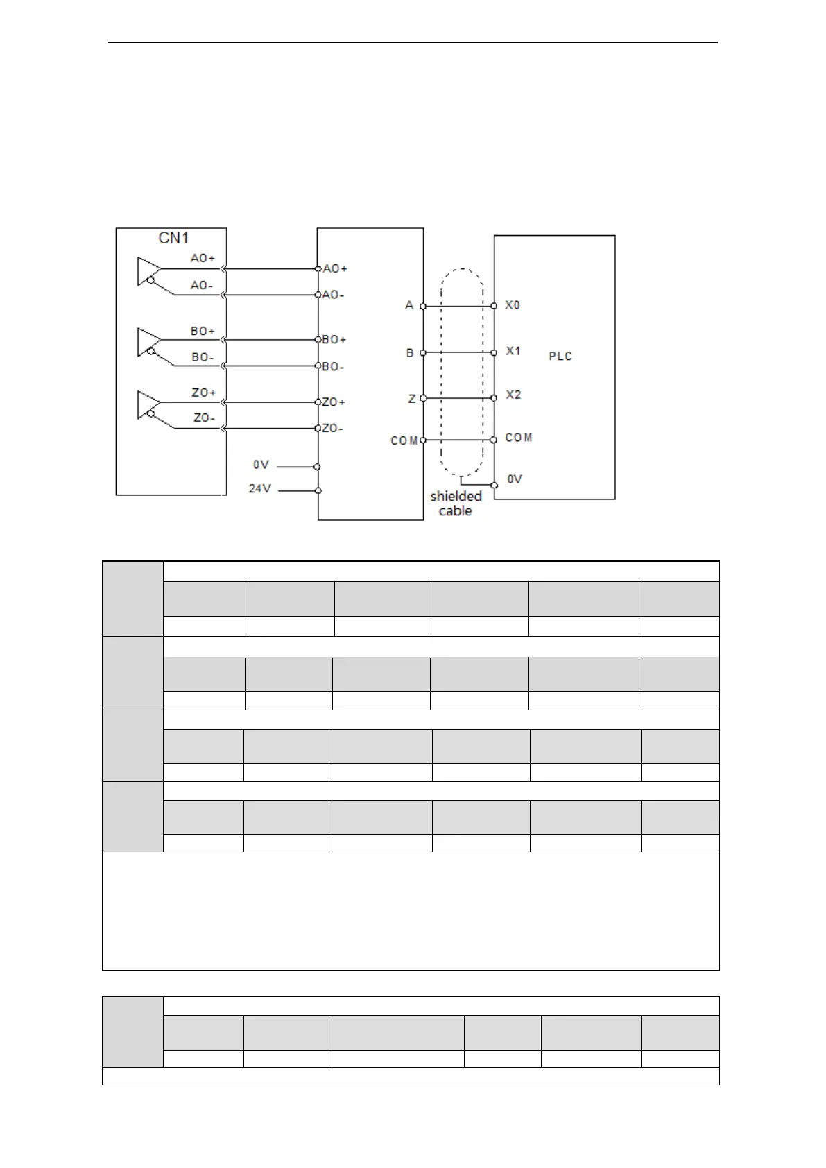
5-11-7. ABZ phase feedback signal of encoder (CN1 15-pin support)
1. Wiring diagram
DS3-2□P□-PQA/ DS3-4□P□-PQA 和 DS3L-2□P□-PQA/ DS3L-4□P□-PQA support differential
output AB phase feedback signal.
Please see the following wiring diagram of DS3-21P5-PQA and Xinje PLC XC3-32RT-E.
Drive CN1(DB15) differential signal to collector PLC
2. Encoder feedback pulses per circle (DS3L cannot support)
Encoder feedback pulse per circle (low bit)
Encoder feedback pulse per circle (high bit)
Encoder pulse frequency division (numerator)
Encoder pulse frequency division (denominator)
Explanation:
1. encoder feedback pulse is decided by P0-18, P0-19. When P0-18=P0-19=0, encoder pulse frequency
division will work. For example, the motor feedback 2500 pulses per circle, P0-18=P0-19=0 P0-20=1,
P0-21=4, the calculation method is (U2-21/22)*P0-20/P0-21.
2. If it is single phase count, the count value is equal to setting value for motor rotating one circle. If it
is AB phase count, the count value is 4 times of setting value for motor rotating one circle.
3. the feedback value should under 10000. If it is larger than 10000, the system will operate as 10000.
Pulse frequency division output direction (DS3E/L cannot support)
0: same to count direction 1: reverse to count direction
 Loading...


